This manual contains information on the basic features, functions, and operation of the Altronic Compute Module – 4000 (ACM-4000).
GENERAL SAFETY AND WIRING PRECAUTIONS
Review the following safety precautions to avoid injury and prevent damage to the ACM-4000 System or any devices connected to it.
WARNING: Deviation from these instructions may lead to improper engine operation which could cause personal injury to operators or other nearby personnel.
● USE ONLY AS SPECIFIED To avoid potential hazards, install and use this system only as specified. Only qualified personnel should perform installation, wiring, and configuration procedures.
● CONNECT AND DISCONNECT PROPERLY Warning – Explosion Hazard. Do not connect or disconnect equipment, connectors, fuses, plugs, etc., unless power has been verified to be off, or unless the area is free of ignitable concentrations.
● PROPERLY GROUND THE SYSTEM The ground terminal on the Input Power connector of each module must be connected to panel ground, which should be the same as engine ground. DO NOT connect directly to common coil ground.
● SINGLE POINT SYSTEM GROUND The power supply minus (-) terminal and the ground (GND) terminal are common. GND must be connected to panel ground. Minus (-) must be connected to power supply minus. Common point is the panel ground which must be the same as engine ground.
● OBSERVE ALL TERMINAL RATINGS To avoid damage to the system and personnel, observe all ratings and markings on the modules. Consult the individual sections of this manual for further ratings information before making connections to the modules.
● MOUNTING/ENCLOSURE The ACM-4000 System must be mounted on a fixed rail in a suitable enclosure.
● POWER AND POWER DISCONNECT
-
Power must be from a Class 2 power source with transient protection or from a 24-volt battery system.
-
The power to the ACM-4000 System must be installed in accordance with the requirements of the National Electrical Code (US) and the Canadian Electrical Code (Canada)
-
Over-current power protection is required for the ACM-4000 System.
-
A separate disconnect for the ACM-4000 System is required. An Altronic Power Management Module (PMM), a fuse block, or circuit breaker, must be used from the source power to the ACM-4000 in the panel.
-
The power disconnect must be marked as the over-current and disconnect for the ACM-4000 System.
OVERVIEW
General
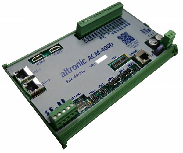
The ACM-4000 (691810-1) is a device used for connectivity, graphical displays, and high end computational power. It combines capable, standard I/O with a unique, configurable web interface to meet the demands of many applications.
Description
The ACM-4000 uses a state-of-the-art System-On-Module (SoM) to centralize: HMI, configuration, control, and networking functions in a single product and combines these with the intuitive Altronic Web Interface to allow for unparalleled adaptability and scalability.
Dimensions
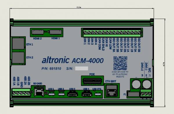
I/O
-
24V Nominal Power
-
3 x Ethernet Ports
-
2 x HDMI Connectors
-
1 x CAN
-
2 x RS485
-
2 x USB C
-
2 x USB A
-
4 x Isolated Relay Outputs
-
4 x Digital Inputs
Web Interface
The system is Ethernet-based, including on-board web pages for system configuration (eliminating the need for a separate terminal program), operation, control applications, and remote monitoring. The intuitive system configuration web page operates on a “fill-in-the-blanks” basis whereby the application is not programmed, but configured. The operator selects the appropriate operating parameters for each input channel and defines the operation of the relay control outputs. Additional functionality can be added and configured on when compatible Altronic products are connected by ethernet with the ACM-4000.
Hardware
The ACM-4000 is available as a family of assembly part numbers (depending on application):
● Final Assembly, ACM-4000 (691810-x)
These components are interconnected with CAT5e Ethernet cable assemblies terminated on both ends with an RJ45 connector.
● Ethernet Cable, CAT5 0.3m (12“) (693221-1)
● Ethernet Cable, CAT5 1.0m (39”) (693221-2)
● Ethernet Cable, CAT5 2.0m (79“) (693221-3)
Input Power Requirement
System power requirement is 10-32VDC, 3 amps max.
Operating Temperature
Ambient temperature range: –40°C to +85°C (–40°F to +185°F)
CSA Information
Class 1, Division 2
Groups A, B, C, D T4
Rated 11-32V, 0.54A
Operating Temperature Range –40°C to +85°C (–40°F to +185°F)
Note: Electrical Ratings are based on the amperage drawn during the full-load of available interface components to the ACM-4000, not the input power requirements.