Connection and Interface Instructions

Altronic Web Interface Overview
In order to commission and interface with Altronic systems a webpage application AWI (Altronic Web Interface) has been designed for all new and legacy products. While there are some benefits of being online for the latest updates and build options, its main intent is to be fully functional off-line while still hosted in a browser window.
There is no need to download any third party software, or worry about updates to your operating system. This new Altronic Web Interface replaces the traditional “terminal program”. One additional feature of the AWI tool is that it very easily becomes the same view for a permanently mounted display, which will be discussed further in this document.
AWI applications
Once connected based on the tutorial below, an AWI application will need to be launched. As discussed the AWI is based on a web browser approach. The full AWI can be downloaded individually and then configured, or individual product specific instances can be downloaded as a starting point and then modified.
These can be found on the downloads page of the Altronic Public Github repository.
Click here for https://github.com/Altronic-LLC/Altronic-Public-Files/tree/main/Altronic-Web-Interfaces
AWI with a Computer
It is best to set up the network adapter or ethernet port without having the targeted device connected, then plug in the ethernet cable, and lastly power up the device. Once all communications have been established with the AWI and the computer, hot swapping the ethernet and power up/down is not an issue. If all connections are performed for the first time while the device is powered, the device may need to be power cycled once all connections and settings have been made.
In order to communicate with the device over ethernet, the IP address of our computer needs changed.
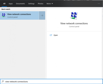
- In windows go to the search bar and type “View Network Connections”’
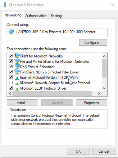
- Find your USB to ethernet adapter and right click on it to find the properties option

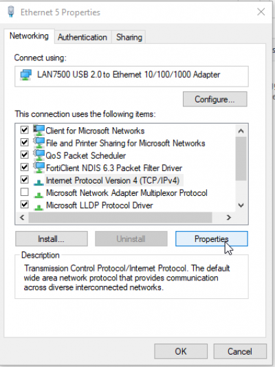
- Under properties, select the (TCP/IPv4) option
- Select properties which allows editing of the (TCP/IPv4) option
- Select “use the following IP address
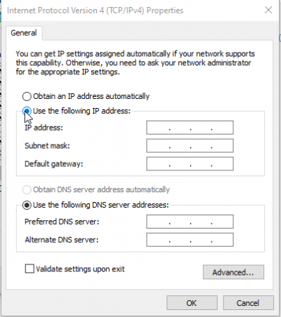
- Enter in the IP address 192.168.1.200

- More than likely the subnet mask will populate automatically, however it should be 255.255.255.0
- Leave the preferred and alternate DNS server options blank
- Click OK
Communication Test – Pinging the Target Device
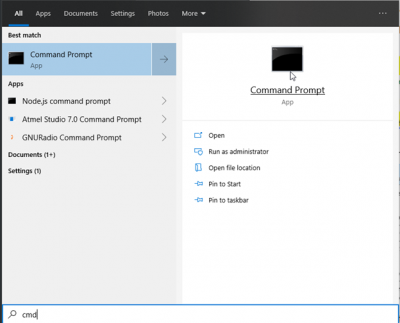
- In windows go to the search bar and type “cmd” to open the command line window application
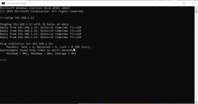
- Type “ping and the associated device IP address”
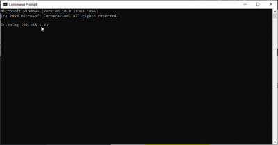
- Press enter and there should be packets sent that match packets received and lost = 0
Connection Parameters
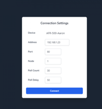
Upon launching the html file a prompt will ask for the connection settings. The device name should already be listed then the following settings need entered.
Address – associated device IP address
Port – 80
Node – 1
Poll count – 30
Poll Delay – 50
After entering these settings, press connect.
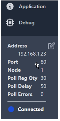
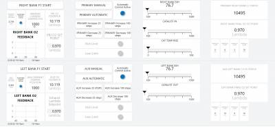
After connecting, the AWI will be launched. A dashboard screen will be visible, and a menu and status bar will be available on the left side of the user’s screen. At the bottom left corner, there will be connection details as shown below. As long as the status says connected and there is a blue light, then the system is communicating with the computer.
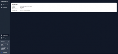
Available views are the dashboard, channels, application, and debug screens. Selecting the application view brings up the builder version that was used to build the dashboard, the name of the terminal window release, and its version information along with the date that it was built.
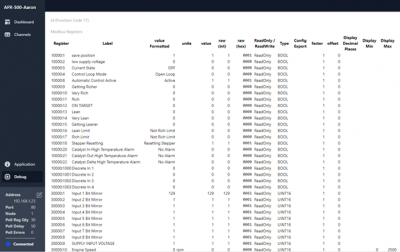
Selecting the debug screen brings up a list view of all available registers which also allows writing into a text field for applicable registers. Additionally, it provides information for the data type and whether the register is read only or read/write.
The Edit Button
The edit button allows the user to add, remove, change, and move elements on the dashboard page. The edit button is available on the dashboard page, but only on a non-locked (non-read only) device AWI (see application exporting options). Also, selecting the edit button allows for the options to import or export a dashboard.

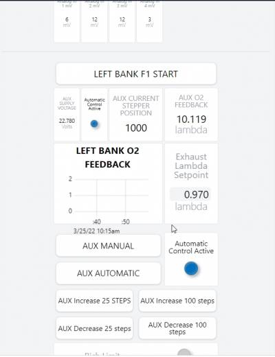
To resize an element on the dashboard, hover your mouse on the right hand corner of the element. If on a desktop, you should see the mouse change to an arrow as shown below.

Next, hold the left mouse button down and drag the mouse in the desired direction to resize the element. Let go of the mouse button to finalize the resizing.

To delete an element, click on the element in edit mode and hit the delete key.
To move an element on the dashboard, left click in the middle of the element and drag the element to the desired location. Elements cannot be moved to another 6×6 grid.
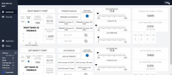
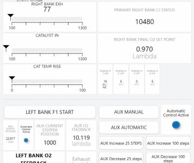
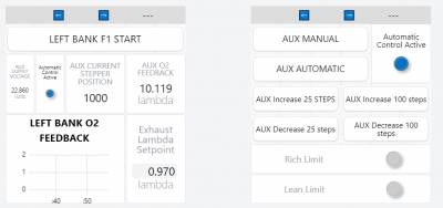
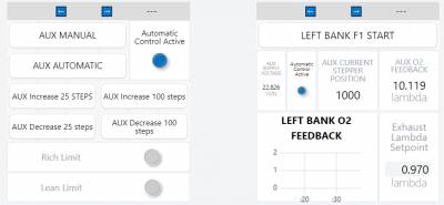
Breakpoints are useful for keeping sections separated. For example, a breakpoint can be added to separate the left and right bank of a dashboard as in the AFR-500. A breakpoint is shown as a gray horizontal bar. When the user resizes the window, the leftmost grid below the breakpoint is always going to be the leftmost grid no matter how the window is resized. The grids after the leftmost grid will flow to the right until there is no more screen space, and then the next grid will be to the left and below.
To add a new breakpoint in the middle of two grids, click the 3 dashes and a new breakpoint will be inserted above the grid you selected. To add a new breakpoint at the end of the dashboard, add a new grid below the last breakpoint. This will add a new section, along with a breakpoint below the new section.

The “Label” text box allows for changing the name of the element that is shown on the dashboard. At first the label will be the register name as shown below.

After changing the label text, the new text will appear on the element. Below, a button is shown before and after changing the label.


Although it is not possible to move a dashboard element from one grid to another, it is possible to move a whole grid of dashboard elements. This is done by selecting the left or right arrows on the top of the grid as shown below.
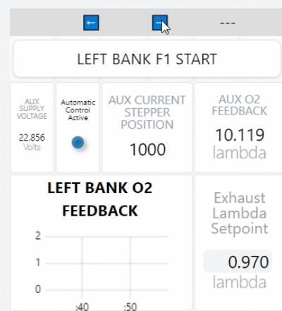
For example, when selecting the right arrow on the grid shown below, the grid is swapped with the grid on the right.
The result after selecting the right arrow is shown below.
Grids can also be moved across the breakpoints, so it is possible to move a grid to a different section.
The Application Tab
The application tab allows for downloading the device AWI with three options along with a name, version, and release notes.
The first export option is locked (read-only) which makes the downloaded device AWI not editable. The edit button will not be available to make changes to the dashboard.
The second option for exporting is “Auto connect” which allows for the device AWI to skip the connect screen and go straight to the dashboard and use the connection settings that were selected before exporting the device AWI.
The third and final option is “Dashboard only” which will export the device AWI without the channel tab, application tab and debug tab available. The dashboard will be wider as a result of not having the additional tabs available.
After all options look correct, click the “Download” button and a .html file with the entered information and options will be downloaded. You can then, distribute or use this .html file as needed. The name, version, and release notes will be in the application tab of the downloaded .html file.
Setting up for DE-4000
Add the AFR-500 as an external device Import the modbus list into the external device configuration
Insert instructions for getting the JSON for the modbus map
When adding the external device you specify the IP address of the device (AFR-500) plus the node appended as a .X at the end of the ip address
Assigning the DE-4000 a secondary IP address that is in the same subnet as the AFR-500
Once the AFR-500 is available as an external device you drop the registers onto any dashboard page
Connect the ethernet cable
If using 485 you select the baud rate and the node.