OVERVIEW
This manual provides operation, configuration, and programming information that enables technicians and installers the information to configure the DE-4000 Safety Shutdown and Control System. Following in typical Altronic tradition, the DE-4000 System is highly configurable without the need for custom programming. For reference, configuration guides the technician to select setup parameters through interactive methods. Programming requires the technician to understand the problem and to write custom code in a programming language to realize a function. Altronic DE-4000 development engineers worked with in-the field application experts to gather critical information that allowed the engineers to develop this comprehensive, highly configurable system. A large number of DE-4000 System applications can be configured without the need for custom programming. However, when a custom requirement is needed, a simple, readable, script type of programming has been implemented in the DE-4000 System.
The DE-4000 Series Configurable Safety Shutdown and Control System must be configured properly before use. Note that damage to the system or to field equipment may occur as a result of incorrect configuration/programming.
The DE-4000 is a web-enabled smart device. It can be configured via the HMI or in a web browser on a standard laptop computer. Another option is to use the Virtual DE to configure the DE-4000 system. The virtual DE is a web-based tool that can be accessed from anywhere that an Internet connection is available. The virtual DE can be used to configure the DE-4000 for the application. The virtual DE allows the user to create a configuration file without physically connecting to the DE-4000 hardware. A configuration file is generated and can be downloaded to the laptop. The file can also be uploaded to the physical DE-4000 System. The Virtual DE can be accessed at the following URL: http://altronicvms.hoerbiger.com. Instructions for accessing the virtual DE can be found on the Altronic website at http://altronic-llc.com/catalogdownloads.shtml, under section “Instruments & Controllers”, click on “Annunciators/Controllers” and scroll to DE-4000 Virtual DE 4-19: Virtual DE Log-on Instructions. Note the quick access link “CLICK HERE TO ACCESS VIRTUAL DE WEB-BASED APPLICATION” can be used to access the Virtual DE.
This manual is organized with a quick start guide, a navigation and layout description, system conventions used throughout the manual, a thorough description for each configuration and application menu in order of the menu structure, and ends with how to import and export a configuration file. This manual is a general configuration/programming manual. It does not provide documentation for every possible solution due to variations in applications and equipment at each location.
DE-4000 SYSTEM DESCRIPTION
The DE-4000 is a Control and Safety Shutdown System specifically designed to protect, monitor, and control critical rotating machinery. Typical machinery includes engine or motor-driven compressors, pumps and generators operating in normal, harsh, and/or hazardous environments.
The system is Ethernet-based including on-board web pages for system configuration (eliminating the need for a separate terminal program to be run on a PC/laptop), operation, control applications, and remote monitoring. The intuitive system configuration web page operates on a “fill-in-the-blank” basis whereby The application is not programmed, but configured. The operator selects the appropriate operating parameters and setpoints for each input channel, defines the performance of the digital and analog control outputs, configures the service meters, and establishes the frequency of system datalog sampling and recording. Programming, via custom scripting, can be written to handle most applications that are outside of the standard configuration selections.
The DE-4000 consists of one Controller Module, a Display Module, and up to five Terminal Modules. The modules are connected to one another via Ethernet communication cables.
Sensors or end devices (analog signals and discrete switches) are connected to the configurable inputs on the Terminal Module. The signals are processed and displayed on the Display Module. System outputs (current loop, and discrete switches) are connected to solenoids, current-to-pressure I/P transducers, etc. The processed signals are used for Safety Shutdown, Alarm, and Control functions.
The system contains an Ethernet connection as well as an on-board WiFi radio to allow for remote monitoring and control. The system, being Ethernet-based, allows for several Ethernet-based electronic devices to monitor and display the information simultaneously—both locally and remotely. System data can simultaneously be displayed on a panel-mounted HMI, a laptop, a handheld display (mobile phone or tablet), as well as remotely.
System Configuration files can be created via a laptop or the HMI Display Module, as well as on the Virtual DE. These files are saved and downloaded to the laptop for use on other DE-4000 Systems. This allows for configuration portability for users operating several similar systems. The files are saved in human readable .json (JavaScript Object Notation) format.
Data logs are taken at user-defined intervals and are a compilation of the analog values being monitored by the DE, plus unit speed, status, and complete information on the first fault that caused a system shutdown (identity, value, date, time). Data log information is stored on a removable uSD card. Data log information can be retrieved locally or remotely. An integral data analysis/trending package that is included with the web interface can display and graph this data for inspection and analysis.
System access to specific functions (configuration, start-up, valve control, and setpoint adjustment) are password-protected. For further information regarding password protection, levels of protection and what is accessible, refer to section 14.4.
NOTE:
REFER TO THE DE-4000
INSTALLATION INSTRUCTIONS,
DE-4000 II, FOR PROPER MOUNTING
AND WIRING.
QUICK START GUIDE
The DE-4000 System is fully configurable and is designed for simple to complex applications. This quick start guide will allow a new user to step through a simple configuration to quickly become familiar with the DE-4000 System and its capabilities. This configuration will use two Terminal Modules, one Controller Module, and one HMI Display. Refer to the DE-4000 Installation Manual DE-4000 II, for instructions on how to install and wire the hardware. Upon installing the DE-4000 hardware, perform the following steps:
Board ID switch
Set the Board ID switch on the first Terminal Module to 1, and the second Terminal Module ID switch to 2.
Dashboard
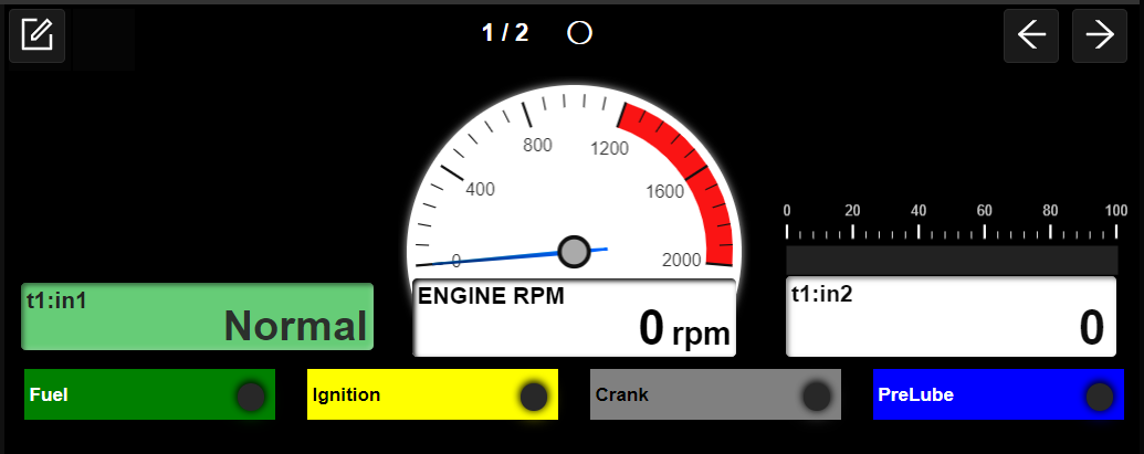
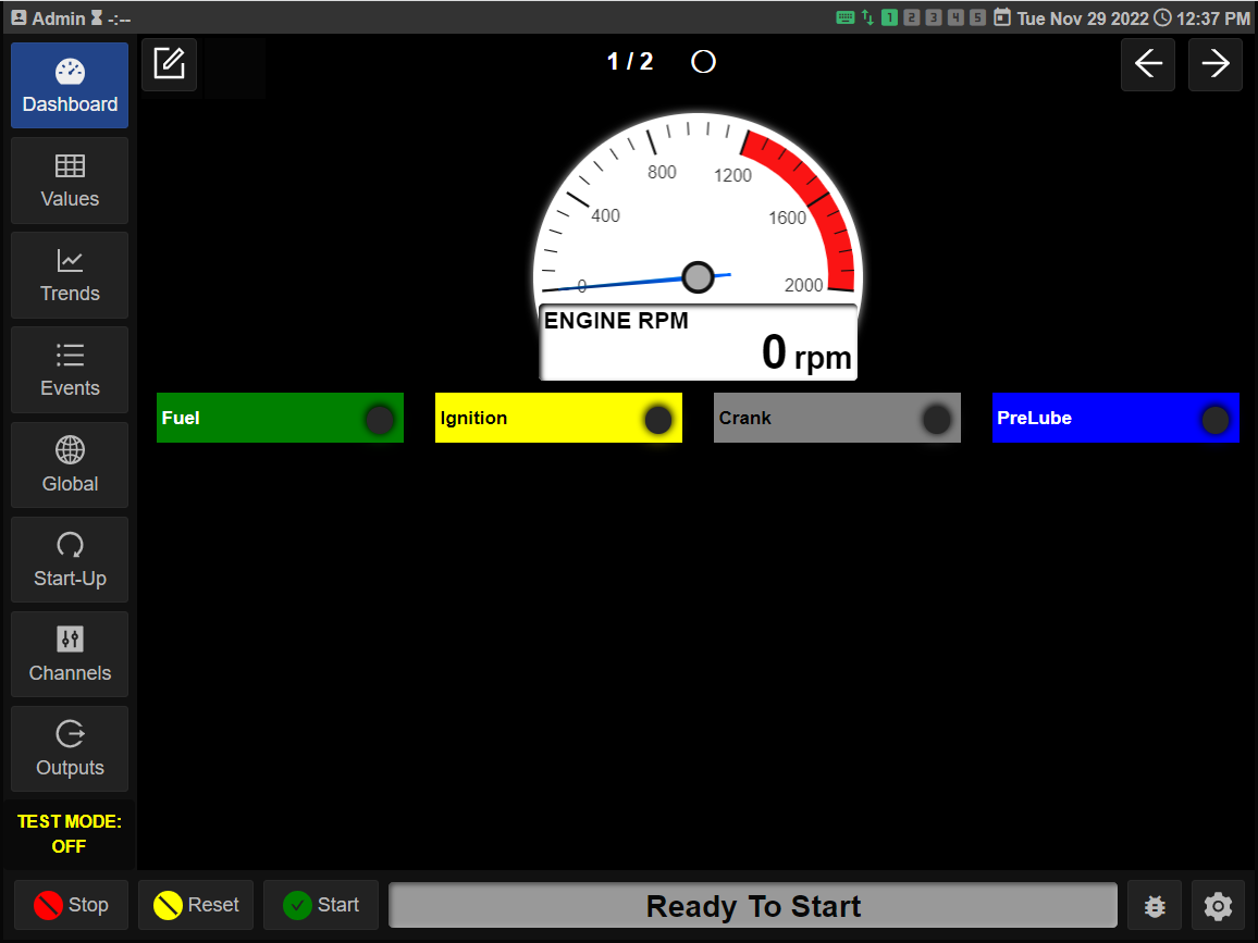
The Dashboard page is displayed on the HMI screen upon system power-up. This is the home page of the DE-4000. The initial view is shown in Figure 3.2.

Configure the Global System Settings
Click on the Global navigation tab to access the system settings.
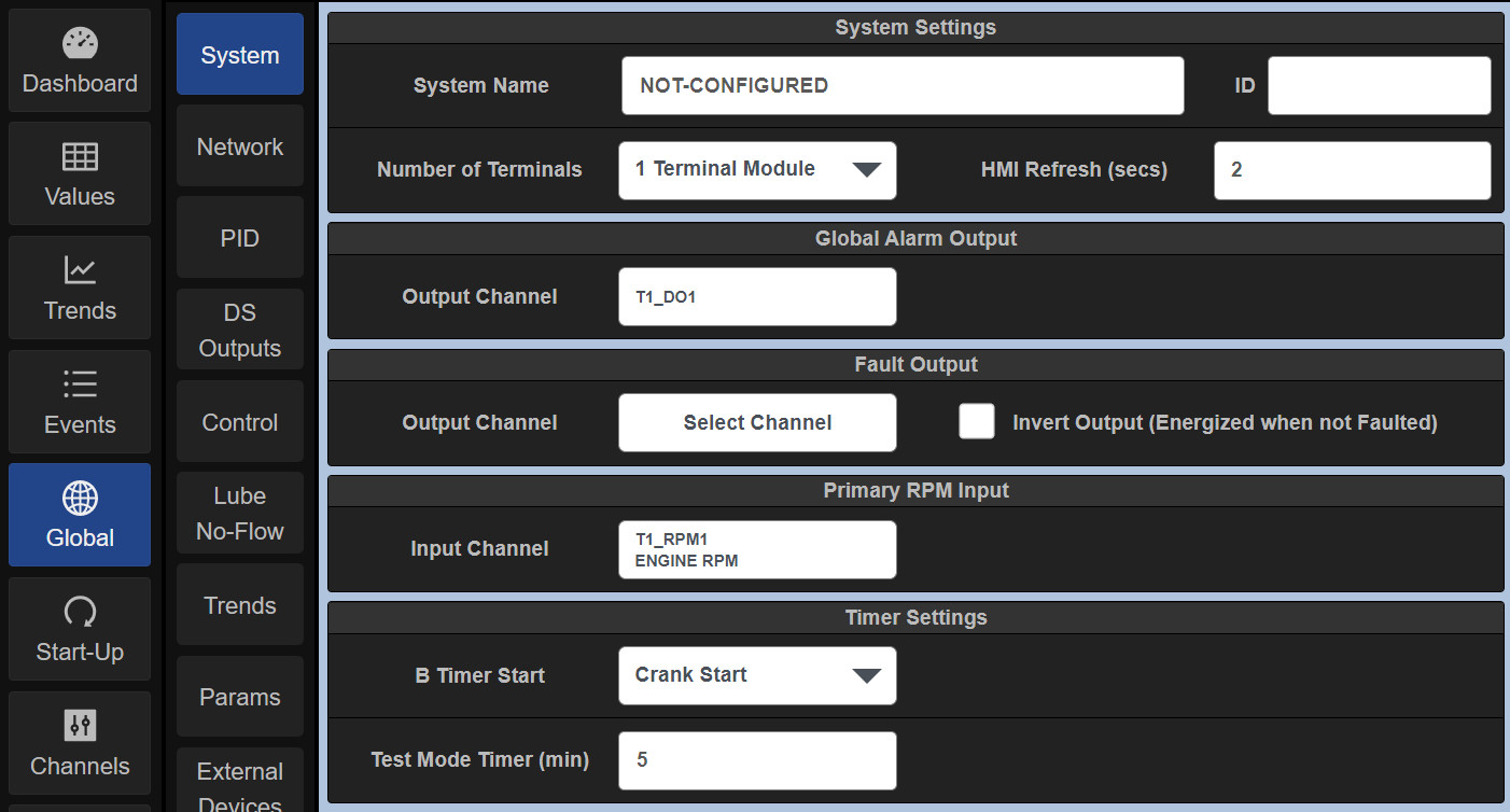
System Name
The System Name typically describes the equipment/system location and can be referred to for configuration, data logs, etc. A typical System Name might be South Compressor Station #2. To access the on-screen keyboard, refer to Section 14.2.
ID
The ID insertion box can be used to assign a unique number to the package or system and can be used to track and identify the system.
Number of Terminals
Select the number of Terminal Modules to be used in the system. Click on the Number of Terminals selection box arrow and select 2 Terminal Modules. Note that when a configuration selection is made throughout the system the selected box will highlight yellow, prompting the user to either Save the change or Revert to the previous value. Once saved or reverted, the change will be saved to memory and the box will return to a white background. The change is not made to the system until the Save button is pressed.
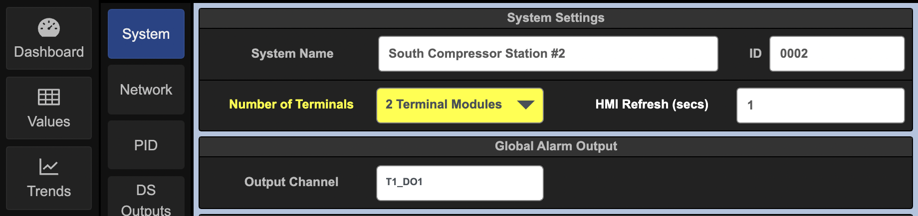
Hard Limit
When logged in as Admin the Hard Limits option allows you to set the Min and max safety limits that a User can adjust. If this option is disabled then the User can not adjust the Safety Shutdown Setpoints at all.
Configure Terminal Modules
Click on the Channels tab and select the TerminalModule to be configured. Select theTerminal X box and select Terminal 1. Note that the Terminal number corresponds to the BOARD ID on the Terminal Module.
Select the Input Channel to be configured
Click on the INX box and select IN1
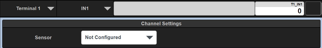
Select Normally Open or Normally Closed
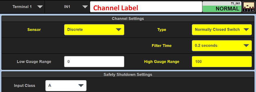
For this example, Select Normally Closed Switch for a Normally Closed Switch type and press Save.
Type a Channel Label
Type a label in the Channel Label box for Channel 1 shown in Figure 3.11. An example may be JACKET WATER LEVEL. Save the changes. Note that this Channel Label is displayed on the Values page, and also the Dashboard page when configured.
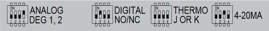
Set the hardware switch on the Terminal Module for each input type
Each channel on the Terminal Module contains a corresponding Input Sensor type hardware switch. The hardware switch must match the configured channel type. For the selected discrete type of input above, set the hardware switch for Channel 1 to Digital NO/NC.
Configure Channel 2
Use the same procedure as above to configure Channel 2, Terminal 1. Click on >CHAN (in the channel navigation bar) or click on INX to access Channel 2. A. Set Channel 2 as a Thermocouple input. B. Select sensor type as Temperature. C. Select K Thermocouple. D. Set the hardware DIP switch for Channel 2 of Terminal 1 to THERMO J or K (Figure 3.12). E. Click Save. Figure 3.13 shows INPUT 2 assigned as a K-Thermocouple.
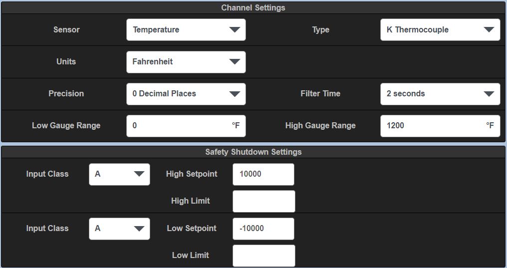
Configure the High and Low Setpoints
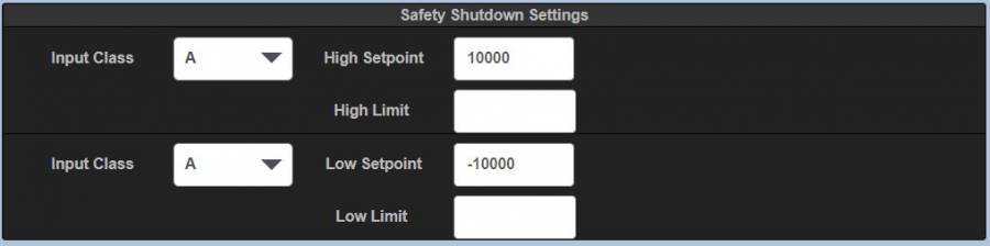
Each channel can have a high and low safety shutdown value, an alarm value, and a control value associated with it. The setpoint values are configured on page one or page two for each channel. In addition, an Input Class must be configured.
Set a safety shutdown value
To set a safety shutdown value, click in the High Setpoint box, for a high setpoint value and/or in the Low Setpoint box for the low setpoint value and enter desired setpoint values for the displayed channel.
Select an Input type
Use the down arrow in the Input Class box to select an Input Class. Note that a separate input class can be set for high and low set-points. Class A, B, or C can be chosen. Note that, for the class B and class C selections, a lockout time can be set. Each input class type is defined below. • Input Class A — Upon a Reset or Start command of the system, a class A input is being monitored and will perform a shutdown on that input if the value violates either a configured low or high setpoint value. • Input Class B — Upon a Reset or Start command of the system, a class B timer will commence. The input will be locked out from causing a shutdown until the class B timer times out. Upon the timeout of the timer, the class B input will be monitored and will perform a shutdown on that input if the value violates either the configured low setpoint or high setpoint. • Input Class C — A class C timer is “Safe until first met”. Upon a Start of the system, an input set to class C will be locked out and the class C timer will commence. The input will be locked out from causing a shutdown until either the input becomes safe and faults again or the class C timer times out. If the input does not clear (continues to be faulted) and the class C timer times out, the input will cause a shutdown to the system. Note that the timer adds a degree of safety for class C inputs in that if the input never clears, without the timer, the input would be an unprotected point.
Configure an RPM Channel
Click on the INX box, a dropdown will appear that contains all of the 32 inputs, DO1-DO8 Discrete Outputs, AO1-AO4 Analog Outputs, and RPM Inputs. See Figure 3.17. A. Click on RPM 1 under the RPM INPUTS. B. Enable RPM 1 by clicking the box and select Yes. C. Type ENGINE RPM in the Channel Label box.
Configure the input channels on Terminal Module 1 and Terminal Module 2
using the same procedure. Remember to change the hardware BOARD ID switch to 2 for Terminal Module 2. Note: The first Terminal Module in the system must be configured as Terminal Module 1, the second as Terminal Module 2, etc. Up to five Terminal Modules can be configured in the DE-4000 System.
Configure the Fuel and Ignition outputs
Navigate to the Controller Module Discrete Outputs screen. Press the Global and then the DS Outputs keys. By default, Output DS1 is the Fuel shut-off output and DS2 is the Ignition on/off output. Configure the outputs’ state by selecting either Energized when Running or Energized when Stopped. The fuel is often configured to be shut off before the ignition. If desired, set a delay time in seconds for the ignition shutoff.
View the configured channels
Click on the Values tab. The Values page shows all of the configured channels in the system (Figure 3.19). The Values page shows a comprehensive amount of information about the configured channels in one location. This is a very handy page to view during start-up, troubleshooting and testing the system. The following information is shown for each channel: A. Channel Label B. Terminal Number and Channel Number C. Current state or analog value D. Units of measure E. Low setpoint and high setpoint values configured
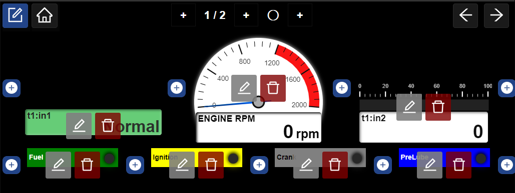
Configure the Dashboard page
The Dashboard page is used as a “Home” page. It can be used to display the most relevant information for each system together on one page. The data can be displayed as several different types of gauges, LED’s, function buttons, etc.
-
Click on the Dashboard tab (Figure 3.21)
-
Click on the Dashboard Edit Icon to edit the Dashboard page.

-
Click on the Home Icon to set the Current Dashboard page as Home.
-
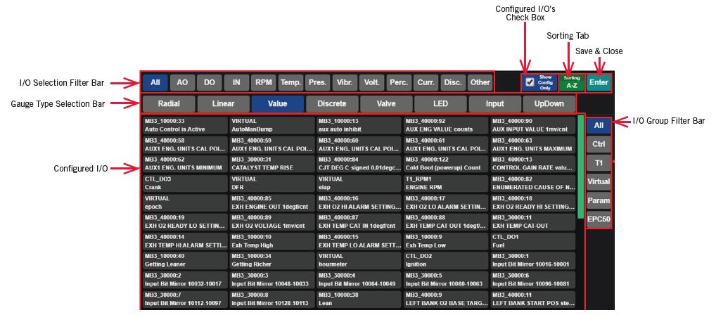
Click on an Add Icon to add an element to the Dashboard.Configured inputs and outputs will be presented along with a range of element types. Select an I/O name and an element type. Press close. The element will be added where the add icon was clicked.
-
Use the Edit Icon to edit an element.
-
Use the Trash Icon to delete an element.
Select an input/output and an element type from the list presented
The list of Inputs/outputs can be narrowed down by using the filters in the right column. See section 6.4 Dashboard Elements for further information on how to use channel screening.

Close the add element editing screen
The elements are automatically saved. Use the Trash icon to delete an element from the Dashboard screen.
Exit the Dashboard editing screen
Upon completion of configuring the Dashboard page, click the edit icon in the top left of the page to exit the Dashboard edit mode.
NAVIGATION AND LAYOUT
The DE-4000 System is designed to be intuitive and simple to use. The interface works the way the user would expect it to. Information is presented the way the user anticipates. Configuration/Navigation menus are always displayed and available. Pertinent information is shown on all screens. Start, Stop, Reset Keys along with a status bar are shown on all screens. System setup is via configuration as opposed to programming. Even though the system is simple to use, it accommodates complex applications with simple straightforward scripting. The following tabs and icons are used to navigate the display menus and to perform actions.
Main Navigation Bar
The Main Navigation Bar, on the left side of the screen, is used to navigate the system. The Main Navigation Bar contains several Navigation Tabs which are described below:
 Dashboard — The Dashboard page is the main configurable homeDE-4000 page of the System DE-4000. The Dashboard page allows the user to customize and display home pages for as many configured inputs and/outputs as desired. Gauges, LED’s, Increase/Decrease buttons, User Input boxes, etc., can be configured for each input or output whether physical or virtual. These elements can be arranged in desired channel or functional groupings .
 Values — The Values page displays all of the configured inputs and outputs.Organization Filters at the top of the screen allow the user to arrange similar types of inputs and outputs to be grouped together. They can be grouped by Terminal Module (TX), Temperatures (Temp.), Pressures (Pres.), Vibration (Vibr.), Percent (Percent),
Current Loop (Curr. Loop), Discrete (Discrete), Other (Other), and All (All).
 Trends — The Trends page shows the selected channel input data over time.

Events — The Events page shows the past and present panel system actions. The actions tracked are Starts, Resets, Stops, and all Faults that have occurred since reset. The first out fault is shown at the top of the list, stamped with the date and time of occurrence and a description of the fault. Faults are displayed in bold text. A colored
symbol is shown that allows the user to quickly identify the type of action shown.
![]() The Fault and Stop symbol is a red triangle with an exclamation point.
The Fault and Stop symbol is a red triangle with an exclamation point.
![]() The Alarm symbol is an Orange Triangle with an exclamation point.
The Alarm symbol is an Orange Triangle with an exclamation point.
![]() A Reset symbol is an orange circle.
A Reset symbol is an orange circle.
![]() The Start symbol is a green circle.
The Start symbol is a green circle.
The most recent faults are displayed at the top. The Event data accumulates and remains in non-volatile memory through a power-down. The max number of events is 200.
 Global — The Global page is used to configure the system settings, System, Network, PID, DS Outputs, Control, Lube No-Flow, Trends, and Params. Descriptions for these subtab functions can be found in section 10.0.

Start-Up — The Start-Up page is used to configure auto start and cooldown. There are ten states from State 0 (Ready To Start) to State 9 (CoolDown). These states are fully configurable.
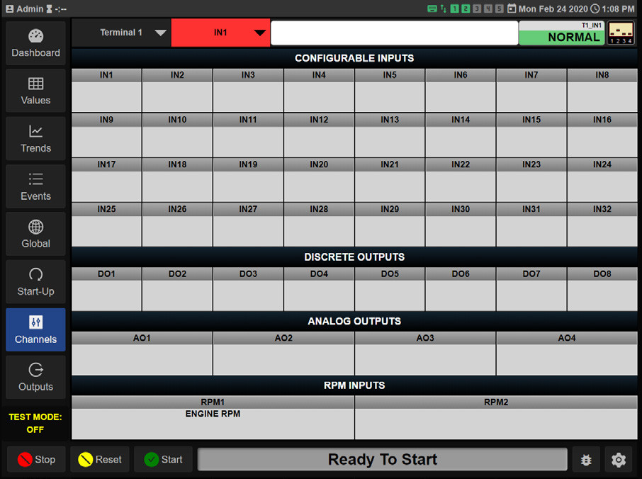
 Channels — The Channels page is used to configure the Configurable Inputs, Discrete Outputs, Analog Outputs, RPM Inputs, Sensor Types, and Setpoint Values, on the Terminal Modules. Select the Terminal Module number and the Input/Output number to be configured.
 Outputs — The Outputs page is used to configure compressor valves; suction, bypass, discharge, recycle, etc. It can also be used to configure solenoid valves, actuators and other electro-mechanical components. Each valve can be configured to open, close, or act per a script for each state. A written script allows for additional functionality. The configured valve or electro-mechanical component performs the
configured action in sequence for each state 1-10. For reference, the states are defined by the startup sequence configured in the Start-up menu. Section 11.0 details the Start-up configuration. Section 13.0 details
the outputs configuration
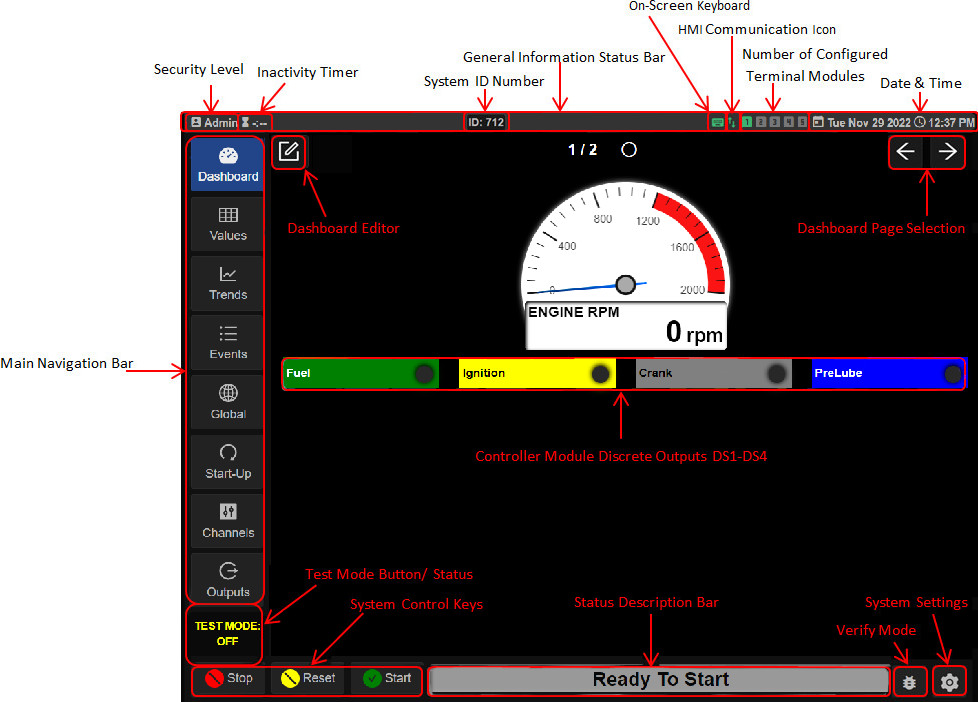
General Information Status Bar
The general information status bar is located at the top of the screen. The General Information Status Bar informs the user of the current general system status. The information status bar displays the current security level, the on-screen keyboard status (on or off), HMI connectivity, the number of Terminal Modules configured, and the system date and time. Changes to the system general information can be accessed in the General Settings page. Press the Gear icon in the lower right corner of the screen to access the system General Settings page. Please refer to the General Settings page below for further descriptions.
 Security Level — The current system security level is indicated at the top left of the General Information Status Bar. The security levels are Factory, Admin, User, and View Only.
 Inactivity Timer — The Inactivity Timer indicates the amount of time remaining on the security level before returning to View Only Mode. This time-out feature is activated when a security password is used. The count-down timer duration is 6 minutes. The timer commences when a password is accepted.
Each key press resets the timer. Upon 6 minutes of keyboard inactivity, the User Level is set to View Only.
The inactivity timer is disabled when no passwords are used.
 System Identification Number (ID) — The ID number is used to identify a Compressor Panel System. The ID number is entered in the ID box located in the Global System subtab. When an ID number is entered, it will be displayed on the General Information Status Bar. The System ID number is saved in the configuration file.
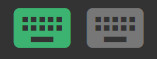 On-Screen Keyboard — The Keyboard symbol indicates the on-screen keyboard status. When the keyboard symbol is highlighted green, the on-screen keyboard is active or on, when gray it is off. The on-screen keyboard is used to enter configuration data when an external keyboard is unavailable. When the system is accessed via a laptop or if a keyboard is plugged into the USB port on the back of the HMI, the onscreen keyboard can be turned off.
 HMI Communication Icon — The HMI communication icon indicates if the Controller Module and the HMI Display Module are communicating. Green indicates proper communication, red indicates communication has ceased.
 Number of Configured Terminal Modules — The number of Terminal Modules configured in the system (1–5) is indicated by the number of highlighted number blocks. The number of blocks highlighted in green indicates the number of Terminal Modules configured in the DE-4000 System. The maximum number of Terminal Modules for a DE-4000 System is 5.
 Terminal Module Communications Error — If a Terminal Board is configured but communications between the Terminal Board and Control Board are not established on power up the Indicator will turn Red. Check Power to Terminal Board as well as the Ethernet Cable.
 Date — The system date is shown on the right side of the Status Bar.
 Time — The system time is shown on the right side of the Status Bar.
Control Keys
Several “soft” control keys are used to Start, Stop, Reset, and Test the system. Start, Stop, and Reset “soft” keys perform the identical action as the corresponding keypad “hard” keys on the front of the DE-4000 Display Module. These control keys are at the bottom left of the screen and are displayed at all times.
 Stop — The Stop key initiates a manual stop condition. When the Stop key is pressed the DE-4000 System will initiate a manual stop function and shut down the system. The status bar will turn red and read Fault Manual Stop.
 Reset — The Reset key clears all past faulted points and resets all input timers to their preset values. The Reset key also returns the system to the Ready To Start state.
 Start — The Start key initiates the Start-Up sequence. Note that a Reset command must be initiated before the Start sequence will take effect.
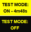 Test Mode — The Test Mode “soft” key is used to place individual channels into the test mode condition. The Test Mode is activated when pressed, a timer starts counting down from the preset value. Testing of each sensor input can be performed without shutting down the system. Upon acknowledgement of the input tested, the timer is reset, and ready for a test on the next sensor input. The test mode in the DE-4000 System is not
a global lock-out test mode. The test mode allows for testing of individual channels while
the system continues monitoring for a fault that may occur on the remaining inputs. The
test is performed when in the Values page. The Test Mode key toggles from ON, with the
preset test time, to OFF with each actuation.
Status Description Bar
The Status Description Bar shows the system state. A text description describes the systems’ current state. The bar also changes color following along with the state description. Please note that the text in each description bar follows the system configuration. For manual simplicity, the states described below are the defaults. The Status Description Bar, when clicked-on, will take the user to the Events page that shows a log of the system events along with dates and time.
 Ready To Start — Ready To Start text indicates the system has been reset and is in state “0”. The system is Ready To Start and is awaiting a start command. The Status Description Bar for the Ready To Start state is colored gray.
 Warning, Pre-Lube, Crank Start, Ignition, Fuel, Crank Wait, Warmup — Upon pressing the Start key the system will proceed with the start-up sequence. The startup sequence states are 1-7. The system will cycle through the configured startup sequence. When cycling through the start-up sequence, the Status Description Bar will show the current state. During the start-up sequence, the Status Description Bar background color is blue, indicating that the system is in the start-up sequence mode. Please note that, during start-up, the Status Description Bar will show the description text configured in the start-up menu.
 Running — Upon completion of the start-up state the system will proceed to the running state. In the running state the Status Description Bar text is “Running “ with a green background. The running state is state 8.
 Fault Manual Stop — Upon a Manual Stop shutdown condition the text describing the cause of the fault will be shown. The background will be red, indicating a fault condition.
 Input Sensor Fault — Upon an Input Sensor Fault shutdown condition the text describing the cause of the fault will be shown along with the value and setpoint number. The background will be red, indicating a fault condition.
General Settings
The General Settings page can be accessed by clicking on the gear icon in the lower right corner of the screen.
 General Settings — The General Settings page allows for enabling the on-screen keyboard, access to Installation and Operation manuals, Bootloader configuration, Import/Export configuration files, password configuration, and adjusting the system date and time.
NOTE: THE DE-4000 SYSTEM CONTAINS A SECURITY-LEVEL SYSTEM.
SOME ITEMS DESCRIBED IN THIS MANUAL CAN ONLY BE ACCESSED BY HIGHER SECURITY LEVELS.
THE SECURITY LEVELS CAN BE FOUND IN THE SECURITY PANE ON THE GENERAL PAGE.
Screen Activity Area
The Screen Activity Area consists of the various Dashboard pages and configuration areas.
SYSTEM CONFIGURATION CONVENTIONS
The DE-4000 System uses specific standards throughout the design. Standard DE-4000 System conventions are described below.
Standard configuration and save conventions:
 A configuration box with a dropdown arrow — This is a selection box. Click in the box and make a selection from one of the drop down items.
 Data Entry Box — Use the keyboard/keypad to enter text or numeric data into the data entry box.
 Save Prompt — When an entry in the selection box is changed the selection box will highlight yellow indicating that the change is pending. Press the Save button to save the change or press the Revert button to cancel the change.
Channels Configuration menu navigation:
^ page The up page key is used to navigate to the previous page.
˅ page The down page key is used to navigate to the next page.
< Chan The previous channel key is used to navigate to the previous channel.
> Chan The next channel key is used to navigate to the next channel.
![]() The copy key duplicates the selection and transfers it to the clip-board to be used in conjunction with the paste command.
The copy key duplicates the selection and transfers it to the clip-board to be used in conjunction with the paste command.
![]() The paste key completes the transfer operation of the selected data from the clipboard to the new location.
The paste key completes the transfer operation of the selected data from the clipboard to the new location.
![]() The Cal key is used to calibrate a sensor input.
The Cal key is used to calibrate a sensor input.
![]() The Revert key is used to revert all changes back to the last save
The Revert key is used to revert all changes back to the last save
DASHBOARD CONFIGURATION
Dashboard
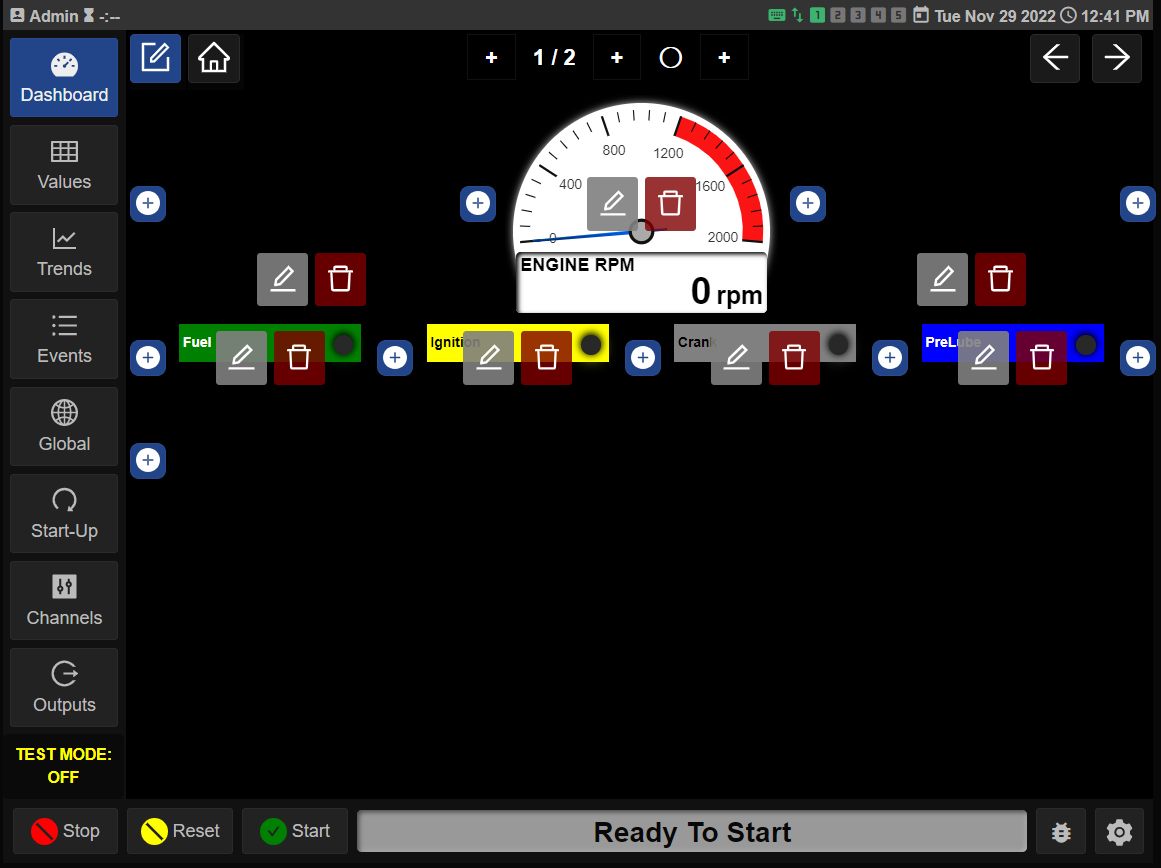
The Dashboard page is used to display selected data in a graphical format in one location for the operator. Any channel can be added to the dashboard page to be displayed. The analog channels can be displayed as analog, digital, and combined gauge types. The digital channels can be displayed as on/off, open/closed, and LED indicators with description. Other types of possible display functions are Increase/Decrease Value arrows, Up/Down arrows, and Input boxes.
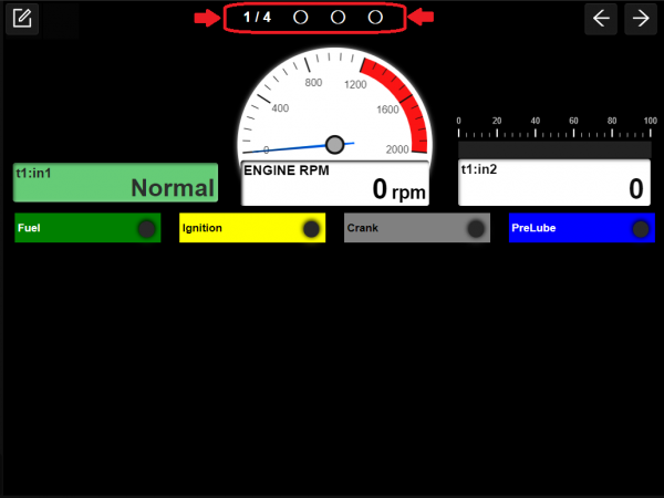
Dashboard Navigation
The dashboard can be created with multiple pages. The multiple pages can be configured with the engine data on one page, the compressor data on another page, the temperatures on another page, etc. Any configured channel can be placed on a page. A maximum of ten Dashboard pages can be created. For multiple Dashboard pages, the viewed page is indicated by the X/X at the top center of the Dashboard page (Example: 1/4 is dashboard 1 of 4 total dashboards). Use the right arrow key to navigate to the next page. Use the left arrow to navigate to the previous page.
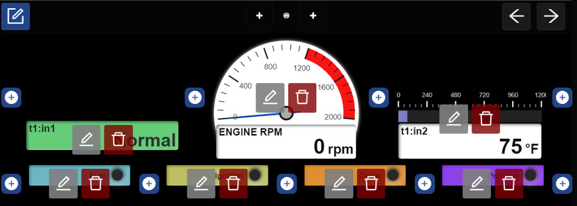
Creating a Custom Dashboard
Use the Dashboard Editor icon to enter the custom Dashboard creation page. Click on the Plus![]()
 icon to add an element, the Edit icon to edit an element, or the Trash icon to delete an element.
Click on the Plus icon to add a gauge to that location, or the Trash icon to delete the location. The gauges will automatically be sized depending on the number of gauges on the rows and columns. As more gauges are added to a row, the size of each gauge will decrease.
Clicking the Plus icon opens a configured channels page as well as a gauge type menu. Select the desired type of gauge and then a channel number, a preview of the gauge will be created. Press close to accept the gauge.
![]() Plus Icon — Use the Plus icon to add a gauge
Plus Icon — Use the Plus icon to add a gauge
![]() Edit Icon — Use the Edit icon to edit a gauge
Edit Icon — Use the Edit icon to edit a gauge
![]() Trash Icon — Use the Trash icon to delete a gauge
Trash Icon — Use the Trash icon to delete a gauge
Dashboard Home Button

 While in Dashboard Edit mode the Dashboard Home select Icon is visible. When the icon is blue the current dashboard is set as Home. When is is black the current dashboard is not set as Home. Only one dashboard can be selected as Home at any time. If the current dashboard is set as Home and you press the Home icon it will turn to black and No dashboards will be set as Home.
-
Dashboard functionality when No Home is selected: If you leave the dashboard screens and go to any other screen like Global, Events, Trends, Etc. then when you return to the dashboard screens you will be on the last dashboard screen you were on before leaving.
-
Dashboard functionality when Home is selected: If you leave the dashboard screens and go to any other screen like Global, Events, Trends, Etc. then when you return to the dashboard screens you will be on the Home dashboard screen.
Dashboard Elements
There are several different dashboard elements available; some are specific for analog values, others for discrete values, and others for control and entering data. The analog specific gauge types are Radial Gauge, Linear Gauge, and Value. Discrete types available are Discrete, Valve, and LED. Control types are Up/Down arrows, and Data Input boxes.
6.4.1 Radial Gauge
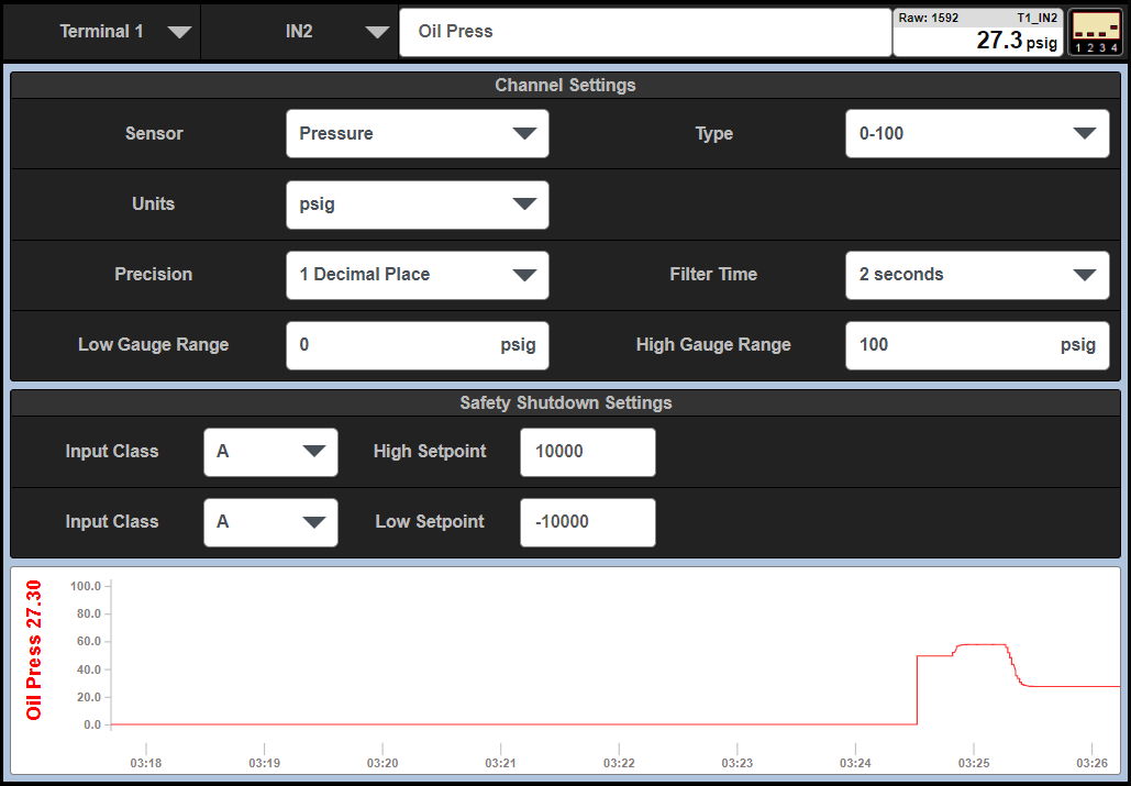
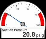 A radial gauge consists of an analog needle-type gauge with configurable upper and lower limit values. Shown also are two red range bars. The low bar extends from min. gauge value and extends to the low safety shutdown setpoint value. The high bar extends from max. gauge value to high safety shutdown value. The configured channel label is shown in the data box below the gauge along with the numerical analog value and units of measure. The background color of the gauge data box is white when the analog value is between the shutdown setpoints and turns red when the analog value violates either the upper or lower setpoint values. The radial gauge is typically used for analog inputs.
6.4.2 Linear Gauge
 A linear gauge consists of a bar type gauge with configurable upper and lower limit values. Shown also are two red range bars. The low bar extends from min. gauge value to low safety shutdown setpoint value. The high bar extends from max. gauge value to high safety shutdown value. The configured channel label is shown in the data box below the gauge along with the numeric analog value and units of measure. The background color of the gauge data box is white when the analog value is between the shutdown setpoints and turns red when the analog value violates either the upper or lower setpoint values. The linear gauge is typically used for analog inputs.
6.4.3 Value
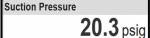 The Value display selection shows the data box that contains the configured channel label, the numeric analog value, and units of measure. Note that the Value display does not show the setpoint values nor change background color if the analog value violates either the upper or lower setpoint values. The Value display is typically used for analog inputs.
6.4.4 Discrete
 The discrete channel indicator is used for discrete inputs. The discrete channel indicator displays the configured label, the Terminal Module and input number, and the current state of the channel. For the current state of a discrete channel, not-faulted reads Normal, and faulted reads Fault. The background color is green when the discrete input is in its normal state (not-faulted), and red when in a faulted state. The discrete channel indicator is typically used for discrete inputs.
6.4.5 Valve
 The Valve channel indicator is used for valve control indication. The valve control indicator displays the configured valve label, the Terminal Module and input number and OPEN when open and CLOSED when closed. The background color is green when the indicator is in its open state, and gray when in its closed state. The valve channel indicator is typically used for valve states.
6.4.6 LED
 The LED indicator is used for a simple on-off indication. The LED indicator displays the configured output label and a state LED indicator. The LED is black when off and green when on. The LED indicator is typically used to indicate output switch status, but can also be mapped to discrete channel inputs to indicate if the channel is on or off.
6.4.7 Input
 The Input box is for the user to enter data, a PID setpoint for example. Typically a numerical value is entered into the user entry box and the action takes place.
6.4.8 Up/Down Button
 The Up/Down button is used to increase or decrease a user input analog value. Pressing the leftarrow key decreases the value, pressing the right arrow key increases the value.
6.4.9 Up/Down Input Button
 The Up/Down Input button is used to increase or decrease a user input analog value. Pressing the left arrow key decreases the value, pressing the right arrow key increases the value. Pressing the center value will open up a keypad to edit the specific value.
6.4.10 Toggle Button
 The Toggle button is used to toggle between two values. Each press of the button will toggle between the two states. Note addition scripting is required to enable this button. See the Scripting manual for more details.
VALUES
Values page
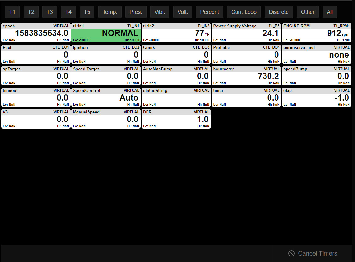
The Values page is used to view the configured channels in the system. The Values page contains a channel information box for all configured channels—including virtual channels and outputs. The data for the Channel Information Box is created by the DE-4000 System when each channel is created. The Channel Information Box displays an extensive amount of information about a channel in one location. The background of the information box will turn yellow when in test mode, orange for an alarm condition, and red for a safety shutdown. Note that a Not Configured channel will not be displayed on the Values page. The channel information box contains the following information:
• Channel Label…..The Channel Label assigned when created
• Tx_CHx …………..The Terminal Module and Channel number
• LO:xxx ……………Low Safety Shutdown Value
• HI:xxx …………….High Safety Shutdown Value
• XXX ……………….Analog value with units of measure, discrete state faulted or normal, open or closed

Channel Information Boxes Filter
The channel information boxes can be organized for best viewing at any time. Filters can be used to organize the information boxes. The filters can be used to display, for example, only temperatures, only pressures, or only the channels on T1, etc. Use the All selection to view all of the information boxes. These filters are located at the top of the display screen. The filter types behave as follows:
• T1-T5: Displays only the configured channels of the selected Terminal Module.
• Temp: Displays only the channels configured as “Temperature” of all connected Terminal Modules.
• Pres: Displays only the channels configured as “Pressure” of all connected Terminal Modules.
• Vibr: Displays only the channels configured as “Vibration” of all connected Terminal Modules.
• Volt: Displays only the channels configured as “Voltage” of all connected Terminal Modules.
• Percent: Displays only the channels configured as “Percent” of all connected Terminal Modules.
• Curr. Loop: Displays only the channels configured as “Current” Loop of all connected Terminal Modules.
• Discrete: Displays only the channels configured as “Discrete” of all connected Terminal Modules.
• Other: Displays only the channels configured as “Other” of all connected Terminal Modules.
• All: Displays all of the configured channels on all of the configured Terminal Modules.
Channel Configuration Shortcut
Clicking on a channel’s Information Box is a shortcut to the channel configuration menu for that channel. The channels configuration can then be viewed and altered if required.
TRENDS
Trends
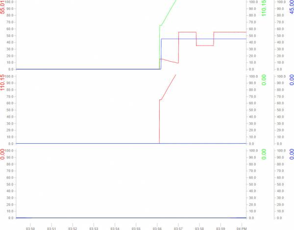
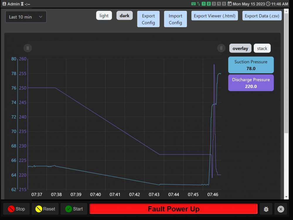
 The trends page can be used to graphically track changing data over time. Data is displayed graphically in line graphs. The line graphs can be used to spot trends in the data collected over time. Data for up to nine separate inputs, outputs, virtual channels, etc. can be tracked. The channel description, value, and max range are shown on the “Y” axis. Time, in 1-second increments, is shown on the “X” axis. The data points are configured in the Trends sub-tab under the Global tab.

8.1.1 Channel Trends
Even if a channel has not been selected for the Trends page it’s last 10 minutes of data can be viewed in the Channel Configuration page at the bottom of the first page. (Only available on Firmware Revision 2.2 and above)
8.1.2 Advance Trending & Data Logging
NOTE: This feature requires an ACM4000 be installed alongside the DE4000.
In Firmware version 3.0.0 and above the standard Trending shown in section 8.1 is replaced with a link to the Altronic Data Explorer(ADE) hosted on an ACM4000 system. Note when showing the ADE the Left side buttons are covered up so the Close button will appear where the Settings gear button usually is. Pressing this will close the ADE and show the left side buttons and the dashboard home page.
If you don’t have an ACM4000 in the system then the Advanced Trending and Data Logging can be disabled by setting a Virtual Channel in the Master Script.

If an ACM4000 is added later the Advanced Trending and Data Logging can be enabled again by setting the virtual channel to “0”.

EVENTS
Events
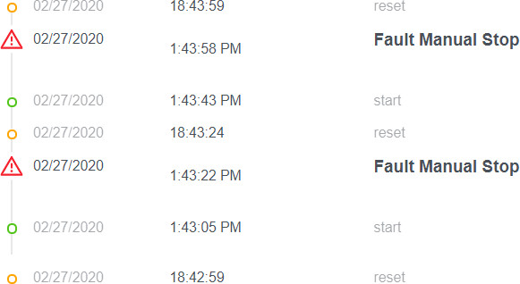
 The Events page displays a log of system events of past and present panel system actions. The actions tracked are Starts, Resets, Stops, and all Faults that have occurred since reset. Most recent events are displayed at the top. The first out fault is shown at the top of the list, stamped with the date and time of occurrence and a description of the fault. Faults are displayed in bold text. A colored symbol is shown that allows the user to quickly identify the type of action shown.
![]() The Fault and Stop symbol is a red triangle with an exclamation point.
The Fault and Stop symbol is a red triangle with an exclamation point.
![]() The Alarm symbol is an Orange Triangle with an exclamation point.
The Alarm symbol is an Orange Triangle with an exclamation point.
![]() A Reset symbol is an orange circle.
A Reset symbol is an orange circle.
![]() The Start symbol is a green circle.
The Start symbol is a green circle.
The most recent faults are displayed at the top. To view the events not currently displayed, use the mouse scroll wheel, or swipe up or down on the HMI. The Event data accumulates and remains in non-volatile memory through a powerdown. The max number of events is 200.
GLOBAL CONFIGURATION
Global Configuration
The Global Configuration menu is used to configure the system global settings. The Global tab contains several submenus. These submenus allow the user to configure the particulars for each function. The submenus are System, Network, PID, DS Outputs, Control, Lube No-Flow, Trends, and Params. The submenus are System, Network, PID, DS Outputs, Control, Lube No-Flow, Trends, External Devices. Scripts, and Params.
Global System Submenu Settings
 The System submenu allows the user to configure the global System settings.
10.2.1 System Settings
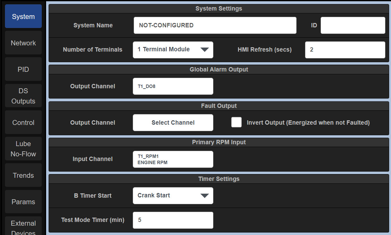
A. System Name — The System Name data entry box is used to identify the panel or package at a location. The System or location name can be specific to each panel and package. A typical label might read: Holt Compressor Package #3. To access the on-screen keyboard, refer to Section 14.2.
B. ID — The ID insertion box can be used to assign a unique number to the package or system and can be used to track and identify the system. The ID Number is displayed on the General Information Status bar.
 C. Number of Terminals — Use the dropdown box to select the number of terminal modules used for the application. The number of terminal Board ID modules must match the quantity of Terminal Modules used in the system. Up to 5 terminal modules can be used in a system. Please note that the terminal module contains a Board ID rotary switch that must be set accordingly. Terminal Module #1’s Board ID switch must be set to position 1, Terminal Module #2 set to position 2, etc.
D. HMI Refresh — The HMI refresh rate is used to set the number of times per second that the display updates data. For most applications the default value of 0.5 is recommended. The range is 0.25 to 2.0 seconds in 0.25 second increments.
10.2.2 Global Alarm Output
The DE-4000 System contains three setpoint types, Alarm, Shutdown, and Control. If the panel design requires alarm setpoints the alarm setpoints must be mapped to a common output switch on a single Terminal Module. Use the Global Alarm Output Channel selection box to select the Terminal Module number to which the alarm is wired. Click the Output Channel selection box. A configuration selection page pops up where an output can be selected. Press close to return and press Save to save the selection.
10.2.3 Fault Output
On typical applications, the fuel and ignition are used to kill the engine; shutdown outputs DS1 and DS2 on the Controller Module are used. For other applications, such as electric motors or Cat engines with the Cat Controller, outputs DS1 and DS2 may be used for special functions and not available for shutdown. In those instances an output on one of the Terminal Modules can be mapped to indicate a “shutdown” fault has occurred. Use the Fault Output Channel selection box to select an output to use as the fault output. Click the Output Channel selection box. A configuration selection page pops up where an output can be selected. Press close to return and press Save to save the selection. Invert Output – The Invert Output check box reverses the state of the output switch. With the box unchecked, the switch is open when running. With the box checked, the switch is closed when running.
10.2.4 Primary RPM Input
Each Terminal Module on the DE-4000 contains two speed inputs. The Primary RPM Input configuration selection is used to select the primary RPM input on which the Start-up sequence and other RPM related functions are based. Use the Primary RPM Input Channel selection box to select an RPM to use as the fault output. Click the RPM Input Channel selection box. A configuration selection page pops up where an RPM input channel can be selected. Press close to return and press Save to save the selection.
10.2.5 Timer Settings
B Timer Start — The DE-4000 System contains a class B Timer. The class B timer is used to lock out sensors that will be faulted on startup from causing a shutdown until the class B timer times out. Typical class B inputs are oil pressure, suction pressure, etc. The DE-4000 The system allows the user to select when the class B timer commences. The selections for B Timer Start are:
A. Start Button Pressed — The class B timer will commence upon the press of the Start button.
B. Crank Start — The class B timer will commence upon the engagement of the crank output switch.
C. Exceed B timer RPM — The class B timer will commence upon the system exceeding a set RPM value. The class B inputs are locked out prior to reaching the configured B Timer RPM plus the class B timeout time configured for each channel. Use the B Timer RPM selection box to enter a RPM value.
Test Mode Timer (minutes) — The DE-4000 System contains a test mode that can be used to test input sensors without faulting the system. A test mode “soft key” is used to initiate the test mode. Each time the test key is pressed, a test timer counts down from the configured test time. The Test Mode Timer value input box is used to configure the test time. The allowable test time range is 0 to 30 minutes.
Hard Limit
When logged in as Admin the Hard Limits option allows you to set the Min and max safety limits that a User can adjust. If this option is disabled then the User can not adjust the Safety Shutdown Setpoints at all.
Network Settings
10.4.1 Modbus Settings
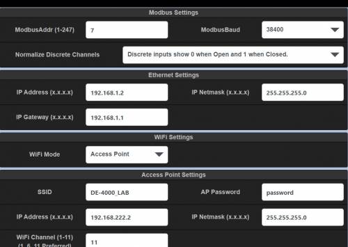
The Modbus Settings pane is used to configure the RS485 Modbus slave communication parameters. The node number and baud rate are selectable. The selectable baud rates are 9600, 19200, 38400, 56200, and 115200. The other parameters are fixed as shown:
| Communication Parameter | |
|---|---|
| Baud Rate | 9600-115200 |
| Node # | 1-247 |
| Bits | 8 |
| Stop Bits | 1 |
| Parity | None |
| Handshake | None |
| Table 10.3.1 – Communication Parameters | |
-
ModbusAddr – Use the Modbus Entry Box to enter a node number. Valid Node Numbers are 1 to 247.
-
ModbusBaud Use the Modbus Selection Box to select a communications Baud rate. (9600 to 115200)
Normalize Discrete Channels — This configuration is used to “normalize” the Modbus discrete channel bits read by a SCADA System to be all “0’s” in the normal or non-faulted state and all “1’s” when faulted. By default the Modbus discrete channel bits are “0’s” when the input is open and “1’s” when closed. This feature is useful when the system contains mixed normally-open and normally-closed discrete inputs by sending the bits that represent the normal condition as “0’s” and the faulted condition as “1’s”.
10.4.2 Ethernet Settings
The Ethernet settings are used to configure the Ethernet port to allow the DE-4000 System to communicate to externally connected devices.
IP Address — The IP (Internet Protocol) Address is an identification number assigned to the DE-4000 network hardware to allow external devices to talk to the DE-4000 outside of its internal network. For example, a SCADA system, acting as the Modbus Master can use this IP address to communicate to the DE-4000 as the slave. The default IP Address is 192.168.1.2
IP Netmask — The subnet mask is used to distinguish between the host portion of the IP address and the network. The default Subnet mask is 255.255.255.0.
IP Gateway — The IP Gateway is the network node on the network that facilitates communication with other networks. For networks that do not have a gateway, this should be set to 0.0.0.0. The Default Gateway address is 192.168.1.1.
10.4.3 WiFi Settings
The WiFi Settings section is used to configure the WiFi settings on the DE-4000. There are three options. Disabled, Access point, and Client Mode. The description of each is as follows.
A. Disabled — Disabled mode turns the WiFi radio off. In disabled mode the WiFi radio will not transmit or receive WiFi signals.
B. Access Point (AP) — When the DE-4000 is configured in AP mode, it will become a WiFi access point that any device (laptop, tablet, mobile phone, etc.) can connect to. The name of the network (SSID) can be changed along with the default password.
a. SSID — The name of the Network
b. AP Password — Comes with a default Password that can be changed to a desired password.
c. IP Address — Sets the IP Address that devices connect to.
d. IP Netmask (x.x.x.x) — Can be left to the default (255, 255, 255, 0)
e. WiFi Channel — Channels (1-11) can be used as WiFi channels, with channels 1, 6, and 11 preferred. Channels 2, 3, 4, 5, 7, 8, 9, 10 overlap and can cause problems, whereas channels 1, 6, and 11 are setup to Not overlap.
C. Client Mode — The Client Mode is used to connect the DE-4000 to an existing WiFi network. The client mode can be used to allow SCADA systems to log onto a DE-4000 System. Set the Network to “Other” and enter the SSID Network ID and enter the password.
NOTE:
It is recommended to split-up the number of connected systems equally to each assigned channel.
PID, Proportional – Integral – Derivative Controller
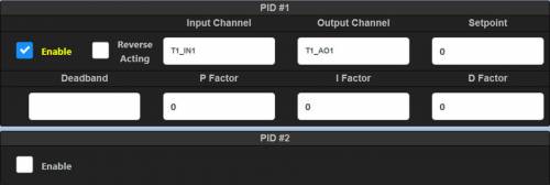
A PID control loop monitors a measured process variable and an error value and continuously corrects for the error between the desired setpoint and the measured process variable based upon the Proportional, Integral, and Derivative values. The P, I, and D terms, along with a deadband value, are used to configure the PID’s correction response to the error. There are several PID control loops in the DE-4000 System. The PID sub-tab is used to configure the PID controller parameters. Up to 10 PIDs can be configured on this screen. The PID Controller can be assigned to virtually any input channel on the Terminal Module. It can then be mapped to virtually any current loop output on any Terminal Module. Any configured pressure, temperature, valve position or other equipment parameter which can be expressed as an analog value from 0 to 5 volts can be controlled by the PID loop. Some typical controlled values would be the discharge pressure of a compressor, the intake manifold pressure of an engine, the temperature of a cooling system or the chemical composition of a process output. Use the following parameters to configure and tune the PID.
10.5.1 Enable
 Click the corresponding Enable check box to expose each PID’s configuration and tuning parameters.
10.5.2 Reverse Acting
 The Reverse Acting check box inverts the current output. When set to Forward Acting, the current output for the low channel value will output 4mA and the high channel value will output 20mA. For reverse acting, the current output for the low channel value will output 20mA and the high channel value will output 4mA.
10.5.3 Input Channel
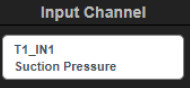 The Input Channel selection box is used to select the desired input channel to be used as the control loop input parameter. Click the selection box to bring up the I/O Selection Page where the configured inputs can be accessed. Make a selection and press the Close button. The Terminal number, channel number, and channel label will be populated in the Input Channel box.
10.5.4 Output Channel
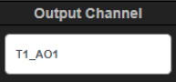 The Output Channel selection box is used to select the desired 4-20mA current loop output to be used. Click the selection box to bring up the I/O Selection Page where the analog outputs can be accessed. Make a selection and press the Close button. The Terminal number and analog output number will be populated in the Output Channel box.
10.5.5 Setpoint
 The setpoint value is the user entered desired control point that the measured process variable controls to. Enter a desired numerical control point value that is within the input sensor range. The units-of-measure is auto-populated from the configured input channel Units selection.
10.5.6 Deadband
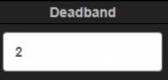 The Deadband is a range around the setpoint, in essence a “window” to which the controller will allow the process variable to deviate without making corrective changes. For example, if the suction pressure is set to 60 psi and the deadband is set to 2 psi, the controller will allow for a suction pressure variation of from 59 to 61 psi without making any corrections. When the process variable goes outside of the deadband the PID controller reacts to bring the system’s output back to the desired setpoint. A deadband value can be used to mitigate noise in the sensor input. The deadband allows the system to ignore the noise in the system preventing the system to react unnecessarily to every blip in the sensors output even if the actual process variable has reached the setpoint. Setting the deadband too high will result in a degradation of control precision.
10.5.7 P Factor (Proportional Factor)
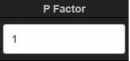 The proportional value determines the reaction to the error. The proportional factor adjusts the gain of the control loop (Gain = 100/proportional band). The larger the Proportional Band, the slower the response time of the control loop. Conversely, a smaller Proportional Band means faster response time. Response time is the time required to return the input to its setpoint. Note that too fast a response time may cause an unstable response.
10.5.8 I Factor (Integral Factor)
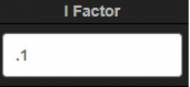 The integral value determines the reaction based on the sum of the recent errors. The Integral Factor proportionally accelerates the correction between the measured process value and the desired value. The integral term is proportional to both the magnitude of the error and the duration of the error. The larger the I Factor, the slower the response time of the control loop. Conversely, a smaller I Factor means faster response time.
10.5.9 D Factor (Derivative Factor)
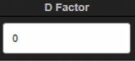 The derivative value determines the reaction based on the rate at which the error has been changing. The derivative factor calculates the error between the measured process value and the desired value by using the error over an amount of time and applying a gain. The larger the D Factor, the faster the response time of the control loop. Conversely, a smaller D Factor means slower response time.
DS Outputs
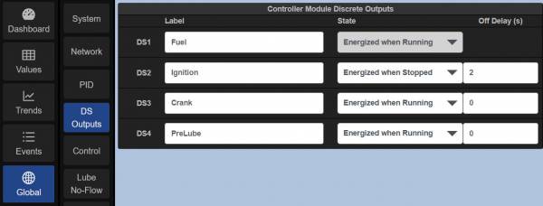
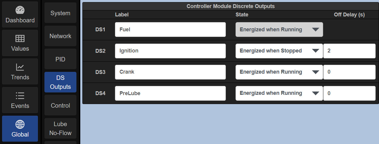
DS Outputs (Controller Module Discrete Output Settings) — The DS Outputs sub-tab is used to configure the four discrete outputs on the Controller Module. The four outputs are DS1-DS4. Each of these discrete outputs can be relabeled and configured to be Energized when Running or Energized when Stopped. Note that DS1 is fixed at Energized when Running.
10.6.1 The default functions of DS1 through DS 4 are:
• DS1 – Fuel
• DS2 – Ignition
• DS3 – Crank
• DS4 – PreLube
Note that DS1 is fixed at ‘Energized when Running’. The DS1 output is the safety shutdown output that triggers if the Hardware Safety Loop is invoked or power is lost. For further description on the Hardware Safety Loop, refer to the DE-4000 Installation Instructions, Section 5.14. Group.
10.6.2 Off Delay
An Off Delay is used to delay an output switch from engaging upon a fault condition or for a manual stop. The delay time is entered in seconds. A typical example of where a delay time is used is between fuel and ignition shutoff or kill. A 2-3 second delay is typically used to prevent the DE-4000 muffler from filling up with raw fuel to prevent an explosion on startup. An off delay time cannot be applied to DS1. DS1 is typically the fuel output.
10.6.3 Custom Background Colors on Dashboard
 A typical way to show the status of a DS Output on a Dashboard is to set the dashboard element up as an LED. The LED Background color can be customized by adding the color in parentheses at the end of the label name. Many standard color names are available like (Blue), (Black), (Purple), Etc.
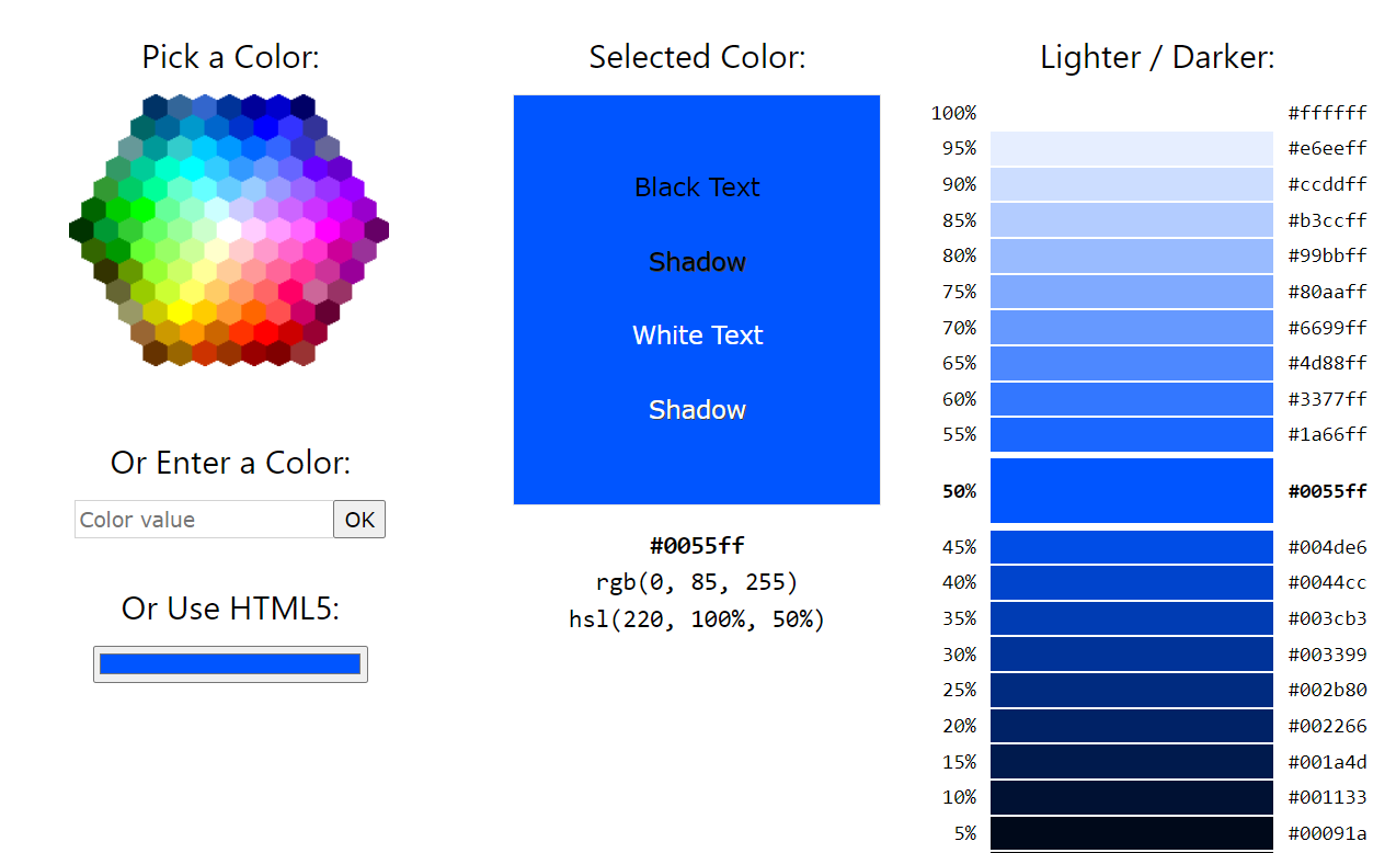
 Or a Hexadecimal Color code can be used.
 A standard HTML Color Picker website can be used to find the proper Hexadecimal value for a specific color.www.w3schools.com/colors/colors_picker.asp

Control (Linear or PID)
 The Control function can be used to control an output or input to a 4-20mA output. A change in the analog input parameter will drive the 4-20mA output between two configured points linearly. Typical applications for linear ramp control are Suction Pressure versus Speed and Discharge Pressure versus Speed. Other typical controlled parameters are Intake Manifold Pressure versus Speed, Engine Temperature versus Cooling Louvers, etc. The 4-20mA output is typically connected to valves or linear actuators to do the actual physical work.
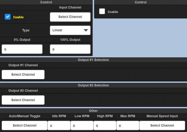
10.7.1 Control
• Enable — Click the corresponding Enable check box to expose the configuration parameters for each Control.
• Input Channel — The Input Channel selection box is used to select the desired input channel to be used as the control input parameter. Click the selection box to bring up the I/O Selection Page where the configured inputs can be accessed. Make a selection and press the Close button. The Terminal number, channel number, and channel label will be populated in the Input Channel box.
• Type — Select Linear or PID.
• 0% Output — Enter the 0% Output value.
• 100% Output — Enter the 100% value output.
10.7.2 Discharge Based Speed Control
• Enable — Yes enables control, No disables control
• Input Terminal — Use the selection box to select the Terminal Module to be used for control
• Input Channel (1-32) — Insert an analog input channel to be used for control.
• Discharge Setpoint — The Discharge Setpoint is the target value. When discharge pressure reaches this setpoint, the system will run at full, but if this value is not met, the system speed will increase until the setpoint is met. If the setpoint is exceeded, the system speed is decreased.
• Max Discharge Pressure — The maximum discharge pressure before a safety shutdown occurs if exceeded.
10.7.3 output
The output configuration is used to map the Suction and Discharge controls to an analog output on a configured Terminal Module.
• Output Terminal — Select the Terminal Module to be used for the Output control.
• Output Channel — Select the Analog Output (1-4) to use as the current loop control output for Suction/Discharge control.
10.7.4 Auto/Manual Toggle
A discrete input on a Terminal Module can be used to switch from auto/manual for Suction/Discharge. This allows a discrete input switch to toggle between auto and manual modes for speed control.
10.7.5 The Linear Ramp Control
allows the user to map and configure an analog input to a 4-20mA output. A change in the analog input parameter will drive the 4-20mA output between two configured points linearly. Typical applications for linear ramp control are Suction Pressure versus Speed and Discharge Pressure versus Speed. Other typical controlled parameters are Intake Manifold Pressure versus Speed, Engine Temperature versus Cooling Louvers, etc. The 4-20mA output is typically connected to Valves or Linear Actuators to do the actual physical work.
10.7.6 Suction Control
• Enable — Yes enables control, No disables control
• Input Terminal — Use the dropdown arrow to select the Terminal Module to be used for control
• Input Channel (1-32) — Insert an analog input channel to be used for control.
• Low Suction Pressure Point — Enter the Low Suction Pressure point
• High Suction Pressure Point — Enter the High Suction Pressure point
10.7.7 Discharge Based Speed Control
• Input Terminal — Select the Terminal Module.
• Input Channel (1-32) — Select the Input channel for the Suction Control
• Discharge Setpoint — his value setpoint sets the rate at which the system is running. When this value is met, the system will run at full,but if this value is not met, the system speed will increase until the setpoint is met. If the setpoint is exceeded, the system speed is decreased
• Max Discharge Pressure — Sets the maximum discharge pressure before a safety shutdown occurs if exceeded
10.7.8 Output
• Output Terminal — Select the Terminal Module for the Output
• Output Channel — Select the Analog Output that will trigger, based on the lowest of either the Suction Pressure or Discharge Control values.
10.7.9 Auto/Manual Input
• This allows a discrete input switch to toggle between auto and manual mode for speed control.
Lube No-Flow
 The Lube No-Flow function is designed to monitor, protect, and log data of progressive in-line lubrication systems that are used on compressors, engines, and other equipment. The monitored signal from a cycle switch mounted to a divider block system connects to a DE-4000 Terminal Module input. Each time a signal is received on its input, the DE-4000 System counts and records a cycle from the lube system. It uses this data to calculate and log the amount of lube used. If it does not receive a signal from the lube system in a predetermined time, the safety shutdown output trips and a message displays, stating the absence of lubrication to the equipment. In addition, each event is logged in non-volatile memory and stored for future download. There are two configurable Lube No-Flow channels and two Flow Meter channels. Any input from any Terminal Module can be used for a lube/no-flow proximity cycle switch signal. Set the selected channel Sensor type to Discrete and the Input Class to None. Wire the sensor as a discrete switch input. The Sensor may be wired as either a N/O or a N/C Input. The DIP switches on the Terminal Module must be set as a discrete input (NO/NC, Figure 3.9).
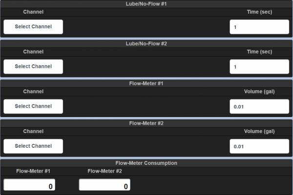
10.8.1 No-Flow Channel
The Input Channel selection box is used to select the desired input channel to be used as the Lube No-Flow discrete input. Click the selection box to bring up the I/O Selection Page where the configured inputs can be accessed. Make a selection and press the Close button. The Terminal number, channel number, and channel label will be populated in the Input Channel box.
10.8.2 No-Flow Time (sec)
The No-Flow Time is used to safeguard the equipment from the absence of lubrication to the lube points. The NoFlow time is compared to the Current Cycle Time. If the No-Flow time is exceeded by the cycle switch time (the absence of pulses from the cycle switch for longer than the no flow time) the system will initiate a shutdown and will show “Lube No-Flow Shutdown” on the Status Description Bar. Use the Time selection box to set a time longer than each cycle time. If the actual cycle time exceeds the configured no-flow time a shutdown will occur.
10.8.3 Flow-Meter Channel
The Flow-Meter monitors the signal from a cycle switch mounted to a divider block system. The Input Channel selection box is used to select the desired input channel to be used as the FlowMeter discrete input. Click the selection box to bring up the I/O Selection Page where the configured inputs can be accessed. Make a selection and press the Close button. The Terminal number, channel number, and channel label will be populated in the Input Channel box.
10.8.4 Flow-Meter Volume (gal)
The Flow-Meter volume entry box is used to enter a volume of lubrication in gallons that represents one complete cycle of the lubrication divider blocks. Each time the DE-4000 System receives a signal from the cycle switch it registers a count. Each count equals a fraction of a unit of measure (gallons). Enter the calculated fraction of a gallon that each pulse represents.
10.8.5 Flow-Meter Consumption
The lubrication consumption for each flowmeter is shown in the flow-meter data blocks.
Trends
 The DE-4000 System contains trend analysis graphing. The trend analysis function can be used to graph and analyze data over time to spot patterns in the data. It can be used, for example, to extract an underlying pattern of behavior in the monitored system that inexplicitly shuts down the system. It can be used to monitor wear levels on bearings, exhaust temperatures between cylinders, etc. A performance comparison can be made graphically to an expected value. Most inputs and/or outputs can be configured to be monitored. Up to three parameters can be graphed on the same graph simultaneously. Up to three graphs can be configured per page.
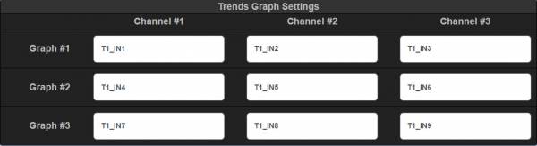
Params
 The Params page is where advanced features code or “scripts” are written to add advanced unique features and functions to the DE-4000 System. Scripting is an advanced feature and is not covered in this manual. Please contact Altronic for scripting support.
External Devices
 The External Devices page allows for additional devices to be monitored. When a Device is configured, it appears under the Active ModBus Devices on the External Devices page. Additional External devices can be displayed on the Dashboard page through the Dashboard Editor. Each additional device is individually filtered through the I/O Group Filter Bar.
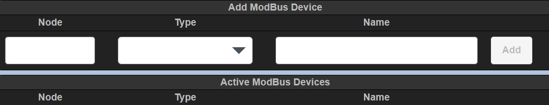
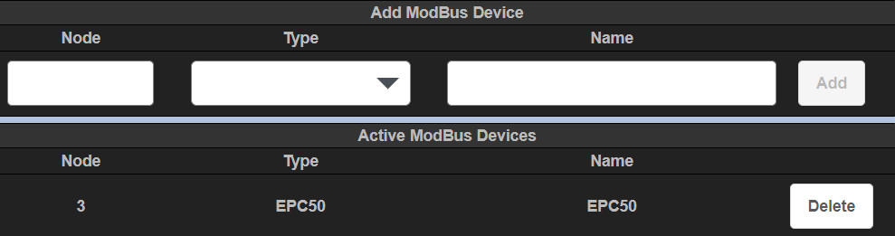
Scripts
 The Scripts page displays all of the main scripts that are on the system. Admin and Factory users are able to select a script and edit it. Scripting is an advanced feature and is not covered in this manual. Please contact Altronic for scripting support.
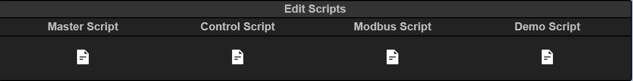
STARTUP CONFIGURATION
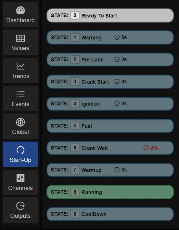
Start-up
Default state labels appear as would be used in a typical start-up state machine. There are ten states that the System steps through in order during startup. The ten states are: Ready To Start, Warning, Pre-Lube, Crank Start, Ignition, Fuel, Crank Wait, Warmup, Running, and CoolDown. Configurable parameters for states are the descriptive label, two timers, ability to map the function to a discrete output upon entry and upon exit of the state, and two permissives.
By default the following discrete outputs located on the Controller Module are used for the auto start sequence.
• DS1 – Fuel Valve
• DS2 – Ignition Shutdown
• DS3 – Prelube
• DS4 – Crank Disconnect
Start-up States:
• State 0 Ready to Start — The system will go to the Ready To Start state when the Reset button is pressed. The Ready To Start state is the state before start — the faults and timers are cleared and the system is waiting for a start command.
• State 1 Warning — The start sequence allows for activation of a warning horn or flashing light prior to engaging the starter. It is recomended that a warning horn or flashing light be activated to inform personnel, who may be present, that a cranking attempt is about to begin.
• State 2 Prelube — Commencement of an electrically-controlled prelube pump for a selected time period prior to cranking.
• State 3 Crank Start — Engine cranking begins when the system enters the Crank Start state. Note that a crank time of a minimum of 5 seconds (5–10 seconds typical) in the Crank Start state is recommended and acts as a fuel purge for the engine before applying ignition.
• State 4 Ignition — Ignition is applied to the engine.
• State 5 Fuel — Fuel is applied to the engine.
• State 6 Crank Wait — The crank disconnect occurs at a configured RPM. A user-programmable crank disconnect speed (set by the permissive setpoint value) switch function will automatically disable the starter at the selected RPM. If the crank disconnect RPM is not reached within the user programmed Timeout period, an OVERCRANK FAULT will be generated turning off the fuel and ignition and disabling the starter until a new AUTO START command is received.
• State 7 Warmup — The warmup speed and period are configured in state 7.
• State 8 Running — The system transitions into the running state upon leaving state 7.
• State 9 CoolDown — The cooldown state is activated by pressing the Stop key, when configured.
Start-Up Configuration
The Start-Up menu is used to configure an auto start sequence. The Start-Up menu is highly configurable. There are ten states that the system steps through in order, from State 0 to State 9. The initial state is State 0, Ready To Start. The Start Key commences the state machine. All configured permissives and timers must be met before transitioning to the next state. To bypass a state, set the timers to 0 and disable the permissives by unchecking the Enable check box.
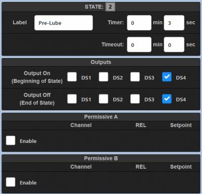
• Label: — Each state contains a text entry box where a word or phrase describing the state is entered. By default each state is pre-populated for a standard startup sequence. For flexibility, each state can be relabeled to meet the requirement.
There are two timers for each state, Timer and Timeout. Both are described below:
• Timer: — The time set in the Timer entry box commences upon meeting the permissives, or if no permissives are configured, by entering the state. The state machine transitions to the next state when the timer reaches zero. If permissives are enabled, the permissives and the expiration of the timer must occur in order to transition to the next state.
• Timeout: — The Timeout timer is used by the system as a protection function, by activating a shutdown condition of the system, if the permissives and the timer time are not met in the allotted Timeout time set. The time in the timeout timer entry box commences upon entering the state. If the Timeout timer reaches 0, the System will shut down and annunciate the label entered in that state as the reason for shutdown. Please note that the difference in time between the Timer value and the Timeout value is the amount of time for the condition to happen to prevent a shutdown.
• Outputs — A configurable discrete output can be turned on when the state is entered and turned off upon exiting the state. Since the output selections are independent of one another, an output can be turned on upon state entry and a different output can be turned off upon state exit.
There are two permissives for each state, described below:
• Permissive A and B — The permissives menus are used to set an analog value or discrete condition from an input channel, such as pressure, temperature, etc. for a condition to be met to either start the Timer countdown or transition to the next state (if Timer is set to 0). An example would be the starter disconnect RPM. Upon entering the Crank Start state a discrete output (DS3 for example) will turn on allowing the starter to engage—rotate the engine— and, when the configured crank disconnect RPM is reached (in the Crank Wait state), output DS3 will turn off, disconnecting the crank motor. This allows for the engine to start by engaging the starter motor, and upon reaching a configured RPM, DS3 will drop out, disengaging the starter motor.
 Enable — Click the corresponding Enable check box to expose each permissive’s configuration and tuning parameters.
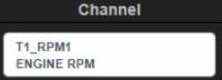 Input Channel — The Input Channel selection box is used to select the desired input channel to be used as the control loop input parameter. Click the selection box to bring up the I/O Selection Page where the configured inputs can be accessed. Make a selection and press the Close button. The Terminal number, channel number, and channel label will be populated in the Input Channel box.
 REL – The REL dropdown box is used to select a >, <, or = operator, used to compare the input channels value to the setpoint value entered. For example, if a greater than operator is selected and the setpoint is 400, the permissive is met when the channel value is greater than 400.
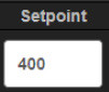 Setpoint – The Setpoint value is the numerical value that is entered that is used as the permissive setpoint value. Its units of measure is related to the input channels units of measure. So if the permissive value is RPM, the setpoint value will be RPM.
CoolDown
Cooldown is state 9 of the startup sequence. Engine cooldown can be configured as part of a normal shut-down of the engine. A PostLube function can be configured as part of the cooldown sequence. Typically DS4 is used as the lube control output. With the PostLube function enabled, use the dropdown selection box to select an output switch on the Controller Module (DSx). Insert a time in seconds to configure the post lube time.
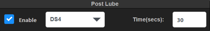
CHANNEL CONFIGURATION
Channels
 The Channels Configuration menu is used to configure the Channel Settings, Gauge Displayed Range, Safety Shutdown Settings, Alarm, and Control Setpoints. The Channels are defined as Configurable Inputs, Discrete Outputs, Analog Outputs and RPM Inputs. Each Terminal Module contains 32 configurable inputs, 8 discrete outputs, 4 analog outputs and 2 RPM inputs. The setpoints contain a fixed hysteresis value around the trip point. Hysteresis values for analog is 2% of full scale, temperature is 10°F, and RPM is 10 RPM.
Channels Configuration menu navigation:
^ page The up page key is used to navigate to the previous page.
˅ page The down page key is used to navigate to the next page.
< Chan The previous channel key is used to navigate to the previous channel.
> Chan The next channel key is used to navigate to the next channel.
![]() The copy key duplicates the selection and transfers it to the clip-board to be used in conjunction with the paste command.
The copy key duplicates the selection and transfers it to the clip-board to be used in conjunction with the paste command.
![]() The paste key completes the transfer operation of the selected data from the clipboard to the new location.
The paste key completes the transfer operation of the selected data from the clipboard to the new location.
![]() The Cal key is used to calibrate a sensor input.
The Cal key is used to calibrate a sensor input.
![]() The Revert key is used to revert all changes back to the last save
The Revert key is used to revert all changes back to the last save
Changes made to an input box are highlighted in yellow until saved. The yellow highlighting is a reminder that a change has been made but not yet saved. Note that changes are not automatically saved. Changes take affect only when the SAVE key is pressed. When highlighted, changes can be reverted back to their original values by pressing the REVERT key.
 Any input box that is grayed out cannot be changed. Typically boxes are grayed out for calculated values based on input values. They will also be grayed out if they cannot be changed because of the security level.
Terminal – X
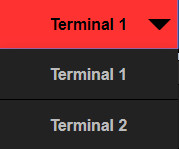 Use the Terminal selection dropdown box to select a Terminal Module to configure. Note that only the Terminal Modules configured in the Global/System page are shown.
INX
Use the I/O selection dropdown page to select inputs and outputs to configure. Clicking on the INX selection box presents all of the I/O channels on the selected Terminal Module. Select a channel to configure.

Channel Name
The Channel Name is shown on the Values page and the Dashboard page as the channel description, and is used throughout the system to identify the channel. Some typical labels are SUCTION PRESSURE, DISCHARGE PRESSURE, etc. Type a name in the Channel name text box.
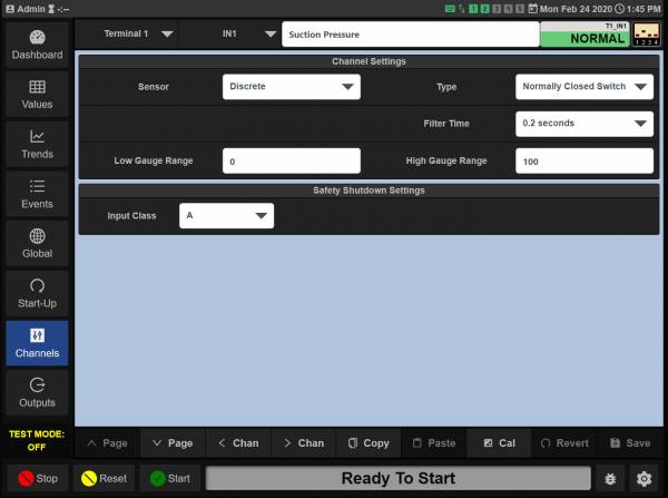
CONFIGURABLE INPUTS
There are 32 configurable inputs available on each Terminal Module. Each input is labeled as IN1 through IN32. Configured channel names will be shown for each input.
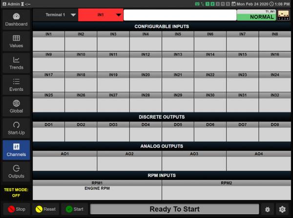
12.5.1 Channel Settings
The Channel Settings menu is used to configure the Sensor, Sensor Type, Units of measure, Precision, Filter Time, and the gauge range. Click in each box to bring up its drop-down selection menu and make a selection. Standard Sensor types are available from the dropdown menus. Select Other for a custom sensor type.
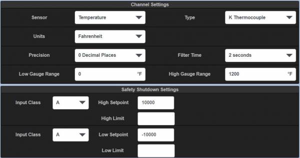
12.5.2 Sensor
Use the Sensor selection box to match the sensor to the physical sensor wired to that channel. The selections are as shown below:
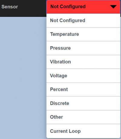
The hardware switch settings for each channel on the Terminal Module must match the sensor to operate correctly. Be aware that a hardware switch settings guide for each sensor selected is shown in the upper right of the screen. Match the hardware switch for each channel on the Terminal Module to the shown switch position
![]()
12.5.3 Type
The Type selection is matched to the Sensor selected. Use the Type selection box to select the type of sensor selected.
12.5.4 Units
The Units selection is matched to the Sensor and type selected. Use the Unit selection box to select the desired units of measure.
12.5.5 Precision
The precision sets the decimal places for the reading.
12.5.6 Filter time
The Filter time is used to vary the amount of change to the input sensor values that can occur from a constantly changing sensor input signal. Changing the filter value has a direct effect on the configured output switch reaction time. The rate of change is less for larger values. The filter value is read-out in seconds, 0.2 seconds being essentially no filter value and 55 seconds being a maximum filter value. Use the selection box to select a filter time.
12.5.7 Low/High Gauge Range
The Low Gauge Range and High Gauge Range are used to set the low and high values displayed on the dashboard gauge. The value of each channel can be displayed as a radial or linear gauge in the Dashboard page. These two points limit the displayed range on the gauge. See Section 6.4 Dashboard gauges.
12.5.8 Safety Shutdown Settings
There are two configurable safety shutdown points for each channel—a high and a low value. The safety shutdown settings are used to prevent unnecessary damage to equipment by detecting an out-of-bounds value and shutting down the equipment. A shutdown sequence is initiated when the input channel value exceeds one of the safety shutdown setpoints. In addition the input can be active on start-up or locked out for a time period for inputs that are normally faulted on start-up, such as oil pressure.
High /Low Safety Shutdown Values — To set a safety shutdown value, click in the High Setpoint box, for the high setpoint value and/ or in the Low Setpoint box for the low setpoint value. Enter desired setpoint values for the displayed channel. Note that if the channel does not require a safety shutdown value, set the value higher than the sensor range. The defaults are 10,000 for the high setpoint and -10,000 for the low setpoint. Since the input value does not reach these values the input is essentially set for no safety shutdown on those channels.
• Input Class — The Input Class dropdown box is used to configure the input to temporarily ignore a faulted input sensor on start-up. There are several different class types that work differently and are defined below. Note that a separate input class can be set for high and low setpoints. Class A, B, or C can be chosen. Note that for class B and C selections a lockout time can be set. The lockout time is entered in seconds. Use the down arrow in the Input class box to select an Input Class. Each input class type is defined below.
o Input Class A — Upon a Reset or Start command of the system, a class A input is continuously being monitored and will perform a shutdown on that input if the setpoint violates either a configured low or high setpoint value.
o Input Class B — Upon a Reset or Start command of the system, a class B timer will commence. The input will be locked out from causing a shutdown until the class B timer times out. Upon the timeout of the timer, the class B input will be monitored and will perform a shutdown on that input if the setpoint violates either a configured low or high setpoint value.
o Input Class C — A class C timer is “Safe until first met”. Upon a Start of the system, an input set to class C will be locked out and the class C timer will commence. The input will be locked out from causing a shutdown until either the input becomes safe and faults again or the class C timer times out. If the input does not clear (continues to be faulted) and the class C timer times out, the input will cause a shutdown to the system. Note that the timer adds a degree of safety for class C inputs in that if the input never clears, without the timer, the input would be an unprotected point.
12.5.9 Alarm Settings
There are two configurable Alarm setpoint values for each channel, a high and a low value. The alarm setpoint values are used to signal a warning for an out-of-bounds value. The alarm condition can notify the operator to take action with the goal of preventing the condition to continue to reach a shutdown condition. An alarm condition is initiated when the input channel value exceeds one of the alarm setpoints.
An output switch on the Terminal Module is used for the Global Alarm Output signal. The output switch can be connected to a horn or other signaling device. Use the Global Alarm Output configuration menu to select the Terminal Module and Output Switch. To map an output— navigate to Global Alarm Output under Global, and then System.
The input class type (lockout on start-up) follows the type set for the Safety Shutdown Settings. Note that if only an alarm setting is desired, the High and Low setpoint values for the safety Shutdown should be set to out of range values so that they will not be reached.
To set an alarm value, click in the High Setpoint text box, for a high setpoint value and/or in the Low Setpoint text box for the low setpoint value and enter desired setpoint values for the displayed channel. Note that if the channel does not require an alarm value, set the value higher than the sensor range. The defaults are 10,000 for the high setpoint and -10,000 for the low setpoint. Since the input value does not reach these setpoints, the input is essentially set for no alarm on those channels.
12.5.10 Control Settings
There are two configurable Control Settings for each channel, a high and a low value. The control settings can be used for simple on-off control. Typical on-off control would be opening a louver at a set temperature. The mapped output switch initiates when the input channel value exceeds one of the control setpoint values. Each of these setpoints, high and low can be mapped to individual or the same output switch on the Terminal Module. The input class type (lockout on startup) follows the type set for the Safety Shutdown Settings.
To set a control value, click in the High Setpoint text box, for a high setpoint value and/or in the Low Setpoint text box for the low setpoint value and enter desired setpoint values for the displayed channel.
Use the Output Channel selection box to map an output switch to the High and/or the Low Setpoint values. Click the Output Channel selection box and select an unused Terminal Module output switch.
12.5.11 Advanced Settings
Advanced settings are used to configure sensors that are not a standard configuration selection in the DE-4000 System. Many sensor types are pre-configured and do not require a settings change in the Advanced Settings menu. Even though the standard selection is comprehensive, invariably there will be a sensor type that is required for an application that is not a standard selection.
To determine if the selected transducer is a standard selection, select a sensor type, Pressure, Vibration, Voltage, etc. Navigate to the Advanced Settings and review the pre-populated Low and High Input Volts, as well as the Low and High Displayed Values. If they do not match the transducer type, adjust these parameters to match the transducer output voltage and range.
An example of a non-standard sensor is a pressure transducer with a range of 0 to 1500 psig with an output voltage range of 1 to 5 volts. For this case, set the Low Input Volts to 1 Vdc, and the High Input Volts to 5 Vdc, the Low Displayed Value to 0 and the High Displayed Value to 1500. The result will be displayed linear values from 0 to 1500 psi over the range of 1 to 5 volts.
Cal settings are available only when logged in as Factory or Admin and should only be used to clear calibration. Use the Cal button to Calibrate the sensor.
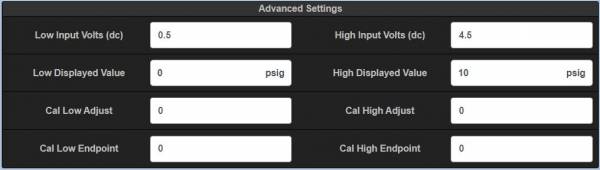
DISCRETE OUTPUTS
There are eight Discrete Outputs per Terminal Module. These can be wired as high side or low side connections. Refer to the DE-4000 Installation Instructions for more information on wiring the Discrete Outputs. The Discrete Outputs are selected/mapped by setpoints and input functions. Setpoints and input functions that can be mapped to Discrete Outputs are:
• Control Setpoints – in the Channels Menu
• Alarm Setpoints – in the Global – System – Global Alarm Output Menu
• PID – in the Global – PID menu
• Outputs configurations – in the Outputs Menu
• RPM Setpoints – in the Channels – RPM Menu
12.6.1 Assigning a label to a Discrete Output
A description name can be given to each Discrete Output. Select a Discrete Output from the Channels Configuration menu. Use the text box next to the Discrete Output selection and type a name for the discrete output. The discrete output can be displayed on the Dashboard page. Using the Dashboard edit menu, configure the output as an LED, a valve condition, or an alarm output indication. The indicator, output name, and state will then be shown on the Dashboard page.
ANALOG OUTPUTS
There are four Analog Outputs per Terminal Module. The analog output range is 4-20mA. The Analog Outputs can be forward or reverse acting. The analog outputs are selected/mapped to PID functions. Setpoints and input functions that can be mapped to Analog Outputs are:
• PID Functions – in the Global – PID Menu
• Speed Control – in the Speed Control Menu
• Suction and Discharge Control – in the Global – Control Menu
• Valve configurations – in the Outputs Menu
12.7.1 Assigning a label to an Analog Output
A description name can be given to each Analog Output. Select an Analog Output from the Analog Outputs menu. Use the text box next to the Analog Output selection and type a name for the Analog Output. The analog output can be displayed on the Dashboard page. Using the Dashboard edit menu, configure the output as a Radial Gauge, Linear Gauge, a Value, or a Valve Condition. The gauge, name, and its value will then be shown on the Dashboard page.
RPM INPUTS
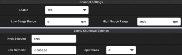
There are two RPM Inputs per Terminal Module. The RPM range is 0 to 65,000, The range depends on several factors—pulses per revolution and ratio. One of the RPM Inputs, for example, can be used for engine RPM, the other Turbo RPM. Each RPM Input can be configured for virtually any standard gear. The number of gear teeth and ratio of speed to speed of interest can be configured.
There are two setpoints, a low and a high, that can be set for each RPM input. The low setpoint can be locked out on start-up by the class timer. RPM control setpoints can be used for discrete RPM points to turn on/off valves, actuators etc.
A primary engine RPM, used for start-up sequence, valve sequencing, etc., must be selected for proper control. The primary RPM input is selected in the Global/ System Menu. A name describing the RPM function should be entered.
The RPM value can be displayed on the Dashboard page as a Radial Gauge, Linear Gauge, a Value Gauge, etc.
12.8.1 Assigning a name to an RPM Input
A name can be assigned to each RPM Input. Use the text box next to the RPM Input selection to insert the name. The name is used throughout configuration and on the Values and Dashboard pages.
12.8.2 Enable
Use the Enable selection box to select Yes to enable the RPM input.
12.8.3 Low/High Gauge Range
The Low Gauge Range and High Gauge Range are used to set the low and high values of the gauge displayed on the Dashboard gauge. These two points limit the displayed range on the dashboard gauge. See Section 6.4 Dashboard Gauges.
12.8.4 Safety Shutdown Settings
There are two configurable safety shutdown points for each RPM channel, a high and a low value. The Safety Shutdown Settings are used to prevent unnecessary damage to equipment by detecting an out-of-bounds value and shutting down the equipment. A shutdown sequence is initiated when the measured RPM value exceeds one of the safety shutdown setpoints. In addition the low RPM setpoint can be active on start-up or locked out for a time period.
• Use the text box to enter a high or low numerical setpoint value.
• Use the dropdown box to select the RPM class (A, B, C) for the low setpoint. Refer to Section 12.5.8 for an explanation of the class types.
12.8.5 Control Settings
There are two configurable Control Settings for each RPM channel, a high and a low value. The Control Settings can be used for simple on-off control. Typical on-off control would be opening a valve at a set RPM. The mapped output switch initiates when the RPM value exceeds one of the RPM control setpoint values. Each of the Control setpoints, high and low can be mapped to individual or the same output switch on the Terminal Module. The input class type (lockout on startup) follows the type set for the Safety Shutdown Settings.
• High /Low Control Values — To set a control value, click in the High Setpoint box for a high setpoint value and/or in the Low Setpoint box for the low setpoint value and enter a desired RPM setpoint value for the displayed RPM channel.
• Output Channel — Use the dropdown box to map the setpoint to an output.
12.8.6 General RPM Setup
The number of gear teeth (pulses per revolution) and ratio of speed to speed of interest (gear speed ratio) for each RPM input can be configured.
• Pulses Per Revolution — The number of gear teeth or pulses per revolution sets the number of pulses the DE-4000 is expected to see in one revolution. Set the PPR to 360 for a 360-tooth gear mounted on the crankshaft. The range is 1 to 1000. Use the Input box to enter the Pulses Per Revolution.
• Gear Speed Ratio — The Gear Speed Ratio is used to set the ratio of gear speed to display speed. When the input is from the crank shaft of the engine the ratio is 1 to 1. If the monitored gear is running 2 times the speed of interest (or display speed), then the ratio is 2 to 1. If the monitored gear is running 5 times slower than the speed of interest or display speed, then the ratio is 1 to 5. Virtually any ratio can be programmed.
• Effective PPR — The effective PPR is the result of or calculated number of the PPR and Gear Speed Ratio inputs. This is an information-only box. There is no user entry in this box.
OUTPUTS CONFIGURATION
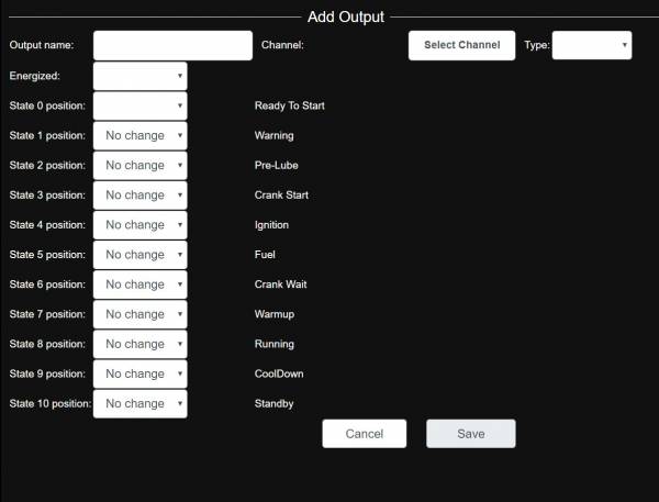
Add Output
 In a typical compressor application, various system control valves are required to cycle from open to closed and back again for a typical startup and shutdown sequence. The Output configuration menu is used to configure outputs on the DE-4000 System to sequence for any of the 10 operating states, from Ready to Start through Standby. Compressor system control valves that are typically controlled by the DE-4000 System are the suction, discharge, bypass, vent, purge, and other valve types. The Outputs configuration menu is used in conjunction with the states configured in the Start-up menu. The state labels created in the Start-up configuration menu will automatically be populated in the Add Output menu for each state. Each valve can be configured to open or close during each system state. The Outputs configuration menu is highly configurable. For each state the valve can be configured to remain in the same state (No Change, Open, or Close) or a Script can be written for extra functionality.
It is required to complete the Output sequence data in the Add Output page for each new added Output “valve”. Once completed press Save to save the new output configuration.
Add or Edit Output
Use the Add Output selection box to configure an Output (valve). Use the Edit Output selection box to configure an Output (valve). Use the Save button to save the configuration, Cancel to ignore the changes, and Delete to remove the Valve configuration. Configure the following items to create an output sequence:
• Output Name — Use the Output Name text box to assign a name to the valve.
• Select Channel — Click the Channel selection box to select an output from the Output Selection page.
• Type — Discrete or Analog
• Energized — Use the Energized selection box to configure whether the output is open when energized (normally-open) or closed (normally-closed) when energized.
• State 1 position thru State 10 position — Use the selection box to select the,desired Output (valve) position for each state. The selections are Open, Closed, No Change, and Script.
Configured Outputs
Pressing the Outputs tab shows the Outputs that are configured in the system. The Output label and type are displayed along with its condition at each state.
X designates that the valve goes to a closed position when in that state.
O designates that the valve goes to an open position when in that state.
![]() designates that a script will run when in that state.
designates that a script will run when in that state.
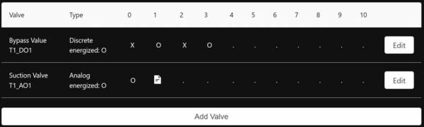
Press the Edit button to edit the current output sequence.
Press the Add Output to add an Output sequence.
![]() Press the script symbol to write or edit a script.
Press the script symbol to write or edit a script.
SETTINGS
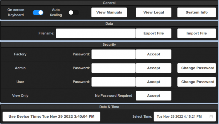

General Settings
The General Settings page is used for miscellaneous information. This page is used to view the DE-4000 manuals, turn the on-screen keyboard on or off, import and export configuration files, configure password permissions, and set the date and time.
Use the gear icon in the lower right of the screen to gain access.
General
The general section is used to invoke the on-screen keyboard and to view the DE-4000 Manuals.
• On-Screen Keyboard — The On-Screen Keyboard is used to enter data into configuration data boxes during configuration of the system when using the HMI Display Module. The on-screen keyboard can be turned off when configuring the system with a laptop or tablet. Another option when the HMI Display Module is used is to plug in a USB keyboard into the USB connector on the back of the HMI Display Module.
o Click the On-Screen Keyboard switch to turn the On-Screen Keyboard ON or OFF.
• Auto-Scale — The Auto-scale is used to stretch the DE4000 User Interface on HMIs larger then 8 inches. With this enabled it will also stretch to fit the browser window when connected through a Laptop.
• View Manuals — The Installation Instructions, Operation and Configuration Manual, Virtual DE Log-On Instructions, etc., are resident and available for viewing and download in the DE-4000 System.
• View Legal — The View Legal tab displays the copyright, license, and usage restrictions of the DE-4000 System.
• System Info — The System Info tab is used to display and update the current firmware/ software version levels or rev levels loaded into each component of the DE-4000 system. If not logged in as Admin the standard System Information page will display the current firmware revisions on all boards and the Current Web Application revision loaded on the SOM. If logged in as Admin the Firmware Update page will display with the interface to allow for updating Firmware revisions on the boards as well as updating the Web Application on the SOM. See Below for instructions on updating firmware.
Non-Admin:
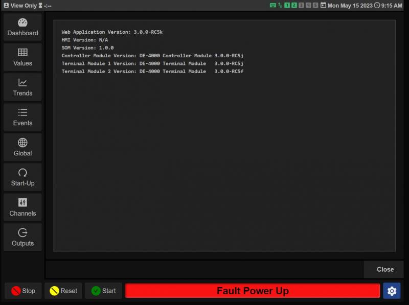
Admin:
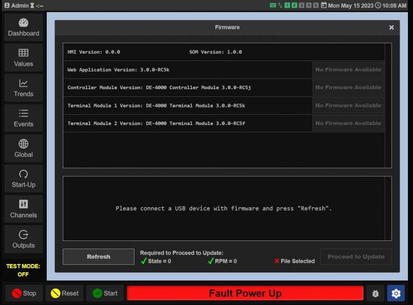
o Web Application — The SOM and Web App Firmware
o HMI — The HMI application settings
o SOM — System On Module, the physical SOM version
o Controller Module — The Controller Module Firmware
o Terminal Module X — The Firmware for each Terminal Module
14.2.1 Firmware Updates
o Updating Firmware/Bootloader — Updating the firmware requires a new version and a USB drive to load it onto the system.

To begin updating, download the new firmware version onto an empty flash drive and insert it into the USB port on the DE-4000. The flash drive needs 30 seconds to mount properly and display the firmware to the Controller Board.
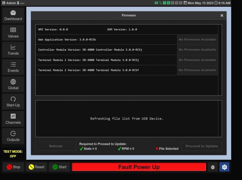
Press System Info to enter the Firmware tab. Pressing the Refresh key in the bottom left should change the buttons to the right of each module version from “No Firmware Available” to “Firmware Available”. This change will only apply to the modules which have updated files in the USB.
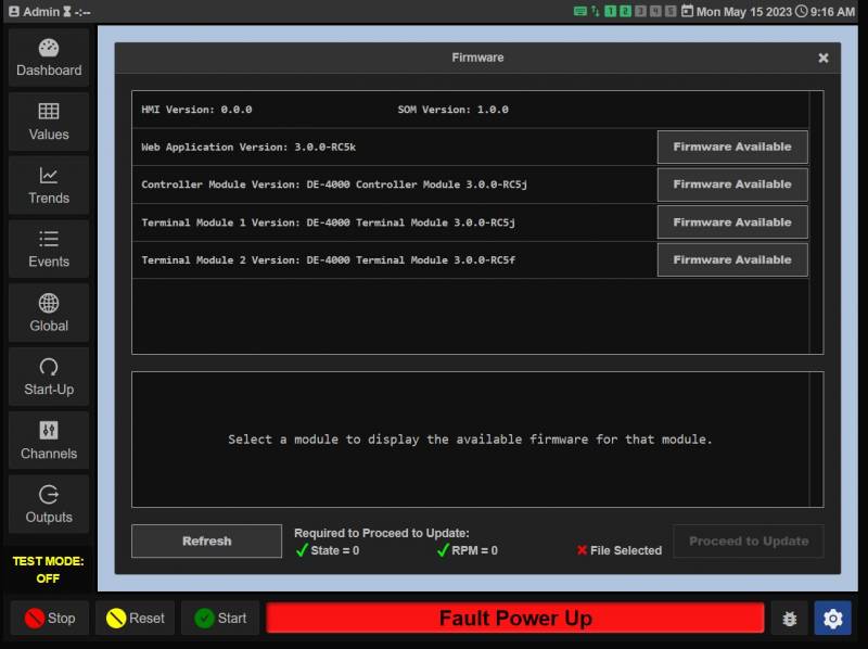
The SOM web app, Controller, and Terminal Boards will all need to be updated separately. Pressing one of “Firmware Available” keys will display the firmware files able to be downloaded to that module from the USB in the menu below.
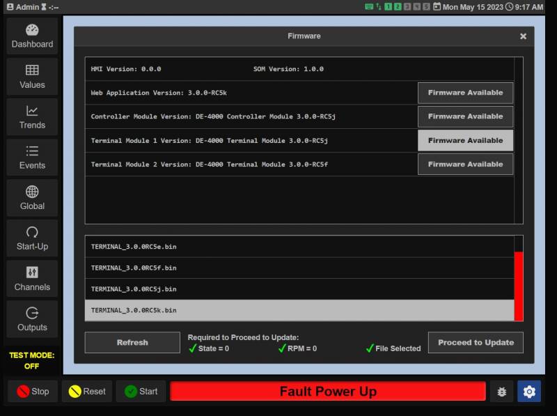
To update after selecting a new firmware, the required conditions are:
o State = 0 — The DE-4000 cannot be in a “Running” state, it must be either “Fault” or “Ready to Start”
o RPM = 0 — All of the Terminal Board RPM inputs must read 0 or be disconnected.
o File Selected — A firmware file must be chosen from the menu
Once all the conditions are met, the “Proceed to Update” button should light up and is now able to be selected.
A Confirm Selection screen will pop up upon pressing “Proceed to Update” showing the chosen firmware and module, press “Proceed” to continue.
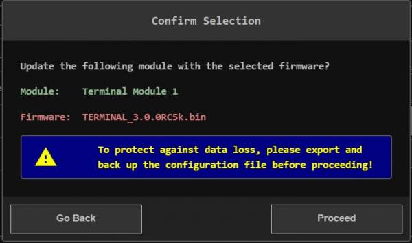
A Lockout/Tagout warning should appear, any connected devices should be locked out to avoid accidents. Press Begin Update in the bottom right to continue.
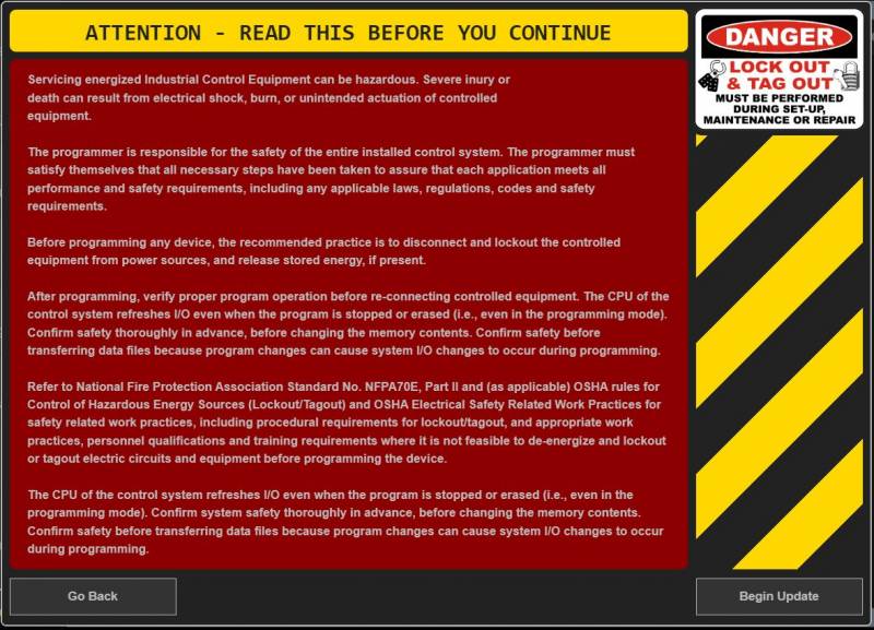
The HMI should display a Progress Bar screen while loading the update.
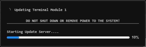
When update is completed a popup message will say that the update was successfully completed. Press close on this popup. If updating a Control or Terminal Board the page will remain on the System info page. If updating the Web Application when you press the close button the web page will do a forced reload to allow the new web application to be properly loaded after the update. This will force the User Interface back to the Dashboard Home page.
The System info page will now display the updated firmware version.
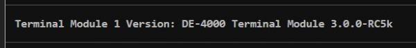
Data
A configuration file contains all of the configurations entered into the system. The configuration file is in a standard data interchange format. It is used to transmit a DE-4000 configuration from one DE-4000 System to another. The configuration file is in a JSON file format. The configuration file is a lightweight, text-based, human-readable format with an extension of .json. The file can be named per standard PC rules. The .json extension does not need to be typed in when creating a name for the file, it is automatically assigned. Configuration files can be created by either the online Virtual DE System or on the hardware itself. The configuration file can be exported (downloaded) on one system and imported (uploaded) to another.
• Import File — Connect a laptop using an Ethernet cable to port 6 on the Controller Module. Use the Import File (upload) box to upload a configuration file saved on the PC. Navigate to the folder that contains the file. The file will have an extension of .json. Select the file and press open. The file will be uploaded to the DE-4000 System.
• Export File — Connect a laptop using an Ethernet cable to port 6 on the Controller Module. Use the Export File (download) box to download a configuration file to a PC. Type a file name into the Filename data entry box and press the Export File box. The file will be saved to the downloads folder on the PC.
Security
System Security can be used to prevent unauthorized individuals from making changes to the DE-4000 via a password system. The current system security level is indicated at the top left of the General Information Status Bar. The security levels are:
Factory — Allows full access to programming, configuration, setpoints, etc.
Admin — Permits configuration, setpoints, etc., but locks out programming.
User — Permits changing of basic setpoints commonly adjusted in the field.
View Only — Permits viewing only
Factory and Admin access allows setup of user passwords.
The security level can be changed by entering the correct password for each level. An Inactivity Countdown Timer is invoked when a security password is used. The Inactivity Timer indicates the amount of time remaining on the security level before returning to View Only Mode. The countdown timer duration is 6 minutes. The timer commences when a password is accepted. Each key press resets the timer. Upon 6 minutes of keyboard inactivity, the User Level is set to View Only. The inactivity timer is disabled when no passwords are used.
Date & Time
The date and time can be adjusted by two methods. Method one is to use the data and time of the laptop connected to the DE-4000. Method two is for the user to set the date and time. In either case, the date and time, once set, are stored and transferred to the onboard date and time system. The date and time are stored in the battery-backed time system on board of the Controller Module.
• Use the Device Time — Press the Use Device Time selection box to use the Laptop PC time to set the DE-4000 time.
• Select Time — Press the Select Time selection box to bring up a data and time calendar. Use the date and time calendar to manually set the DE-4000 System time. Press the OK button to save the date and time to the DE-4000 System.
VERIFY MODE
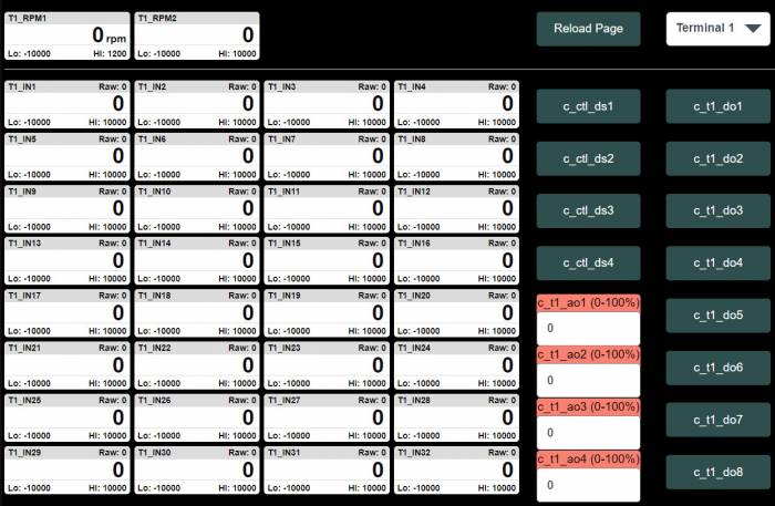

Verify Mode
The Verify Mode is a built-in test mode that can be used to verify input channel data as well as it allows for control of individual outputs for test purposes. To access the Verify Mode, the system must be in the stopped condition and be in an Admin or Factory password level. When in the Verify Mode, all of the Discrete Outputs are placed in the off condition.
15.1.1 Terminal Module Selection
Click in the Terminal x dropdown button to select the required Terminal Module to be verified. The selected Terminal Module inputs and outputs will be displayed.
15.1.2 Input Channels
Live data from the Terminal Board Input channels for each of the thirty-two configurable inputs and the two RPM input channels are shown. Each input channel display box will show the Channel Number (Tx_Inx), the channels live Raw Count Value (an internal reference number), live Sensor Data, Units of Measure, Low and High Setpoint values.
15.1.3 Discrete Outputs
Each discrete output (DO 1-8 and DS1-4) can be toggled from the open state to the closed state. Each corresponding output LED will illuminate.
15.1.4 Analog Outputs
A value entered from 0 to 100% will correspond to the 4-20mA output value for that output. For example, if a value of 50 is entered the output current measured should be 12mA.
IMPORTING/EXPORTING A CONFIGURATION FILE
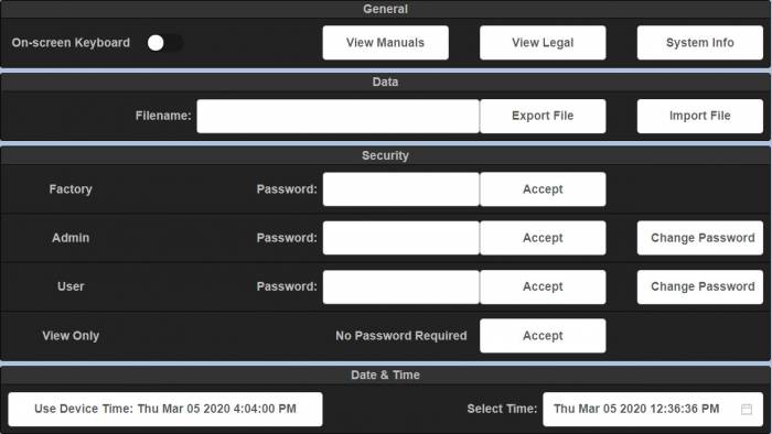

Configuration File Description
A configuration file is used to capture the configuration of the system. The configuration file contains an extension of .json. The .json extension does not need to be typed in when creating a name for the file, it is automatically assigned. Configuration files can be created by either the online Virtual DE System or on the hardware itself. The configuration file can be exported (downloaded) on one system and imported (uploaded) to another.
Importing a Configuration File
Connect a laptop using an Ethernet cable to port 6 on the Controller Module. Use the Import File (upload) box to upload a configuration file saved on the PC. Navigate to the folder that contains the file. The file will have an extension of .json. Select the file and press open. The file will be uploaded to the DE-4000 System.
Exporting a Configuration File
Connect a laptop using an Ethernet cable to port 6 on the Controller Module. Use the Export File (download) box to download a configuration file to a PC. Type a file name into the Filename data entry box and press the Export File box. The file will be saved to the downloads folder on the PC.