SYSTEM DESCRIPTION
OVERVIEW
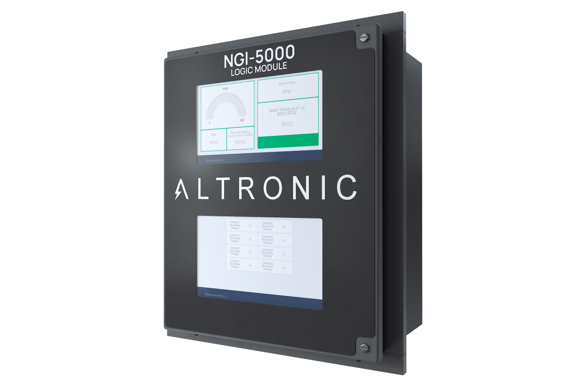
The NGI-5000 Logic Module Legacy Mode is designed to be a drop in, plug and play replacement for the CPU-2000 Logic Module. It comes with two screens hosting information that is exported using the highly advanced Altronic Web Interface (AWI). One screen (bottom) offers a touch interface for interacting with the system, while the other holds static information for quick viewing. Each screen is independent and uses only HDMI and USB for its interface to the overall application. A separate interface is used to program the engine configuration information, this uses web technology and does not require a separate terminal program to be downloaded.
Internally there is an ethernet backbone, and RS485 two wire MODBUS for communications. To power the communications, the displays, and all of the expandability, a System On Module (SOM) is used with high end computing power. In additional to the SOM a time critical and high specification microcontroller is used to interface with the input signals and drive the rest of ignition system.
Since the NGI-5000 Logic Module Legacy Mode is very straight forward, and can be deployed in all CPU-2000 instances, the majority of this document covers CPU-2000 component installation to limit the necessity to go back to the CPU-2000 literature.
SYSTEM COMPONENTS
MOUNTING THE NGI-5000 LOGIC MODULE
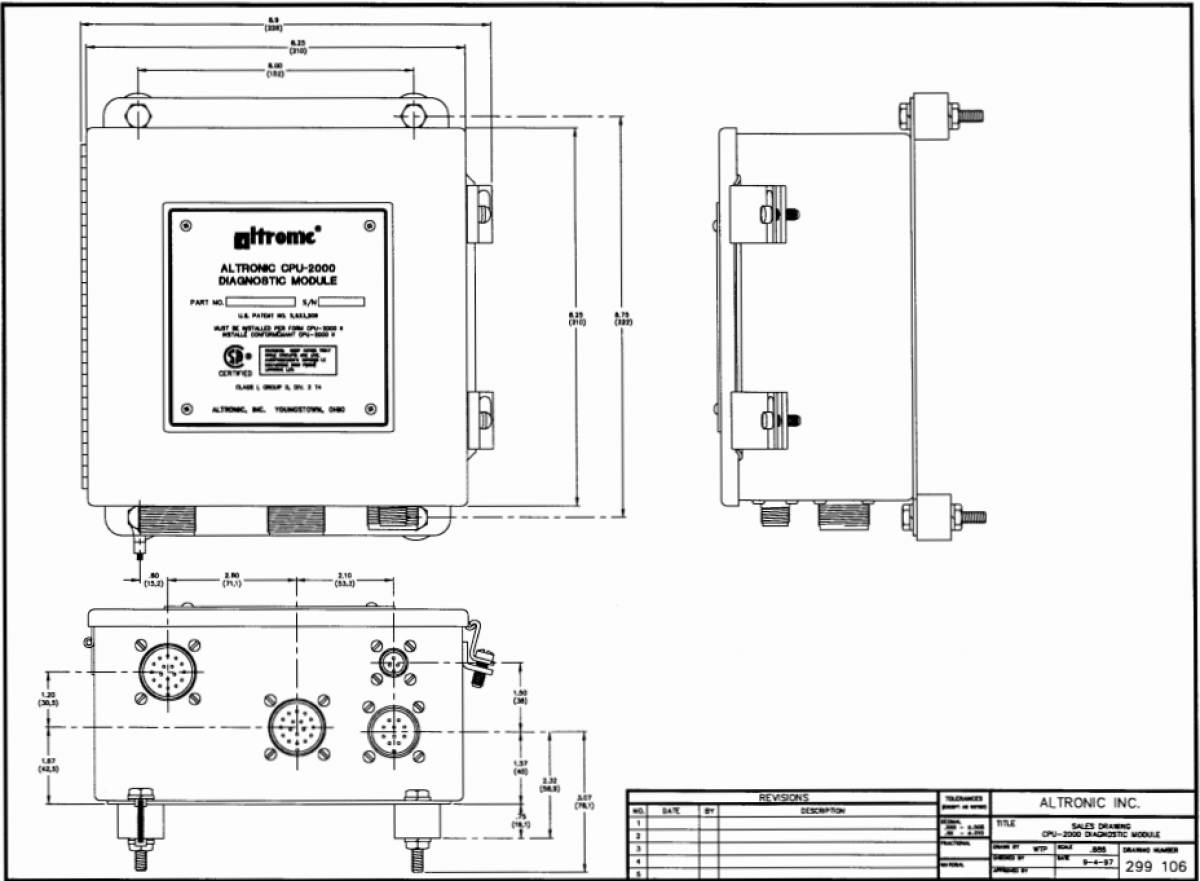
The NGI-5000 Logic Module is preferably panel-mounted off the engine in such a manner as to minimize exposure to vibration. Refer to drawing 299 103 for physical dimension details.
The Logic Module should be mounted within 50 feet (15 m) of the Output Module which is to be mounted on the engine.
Operating temperature range is -40°F. to 158°F. (-40°C. to 70°C.). Humidity specification is 0-95%, non-condensing. Housed in a NEMA 4 enclosure, the CPU-2000 Logic Module is splash resistant; however, the mounting site should provide as much protection from inclement weather as is practical. Avoid mounting the LCD display and keypad in direct sunlight.
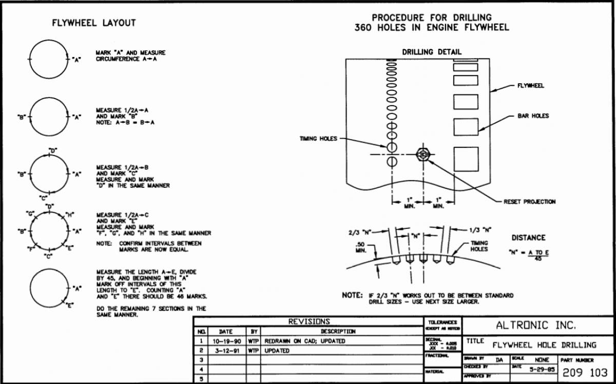
MOUNTING FLYWHEEL GEAR/DRILLING FLYWHEEL HOLES
The Altronic NGI-5000 system requires a source of angular position pulses from the engine crankshaft. This can be a flywheel ring gear, a separately provided gear or specially drilled holes in the flywheel. The source of position pulses must meet the following requirements:
-
Must be ferrous material
-
Diameter of 18“ or greater
-
No. of teeth or holes of 180 or greater
-
Maximum run-out referenced to the pickup of .007
Refer to drawings 209 102A and 209 103 for further details.
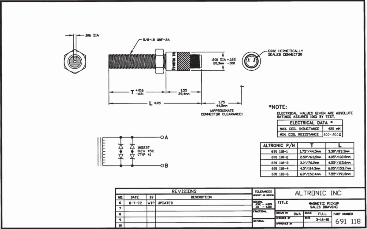
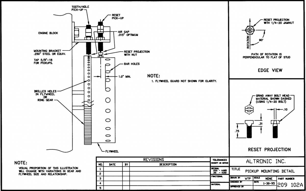
MOUNTING THE MAGNETIC PICKUPS
The system requires two magnetic pickup signals: the angular position pulses from the gear or drilled holes and a reset pulse near the most advanced firing position desired for no. 1 cylinder. The pickups must be mounted to rigid brackets to maintain an air gap of .015” ± .005“ with respect to the rotating gear or flywheel. It is also important for maximum signal efficiency that the centerline of the rotating part pass through the center of the pickup – see drawing 209 102A.
MOUNTING THE FLYWHEEL RESET PIN
Set the engine with no. 1 cylinder six (6) degrees ahead of the most advanced firing point. Mark a point on the flywheel directly opposite the pole piece of the reset magnetic pickup; then rotate the engine to a position convenient for drilling and tapping the flywheel at the point marked above. The reset pin should be made from a steel (magnetic) 1/4”-20 bolt or stud. See drawing 209 102A for details.
Rotate the engine to the original set point and adjust the air gap between the end of the reset pin and the magnetic pickup at .01 O“ using a feeler gauge.
MOUNTING THE CYCLE TRIGGER (4-CYCLE ENGINE ONLY)
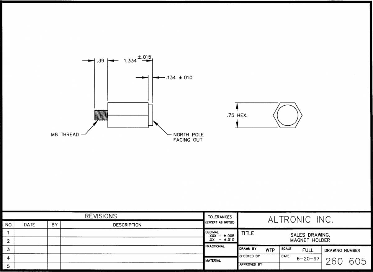
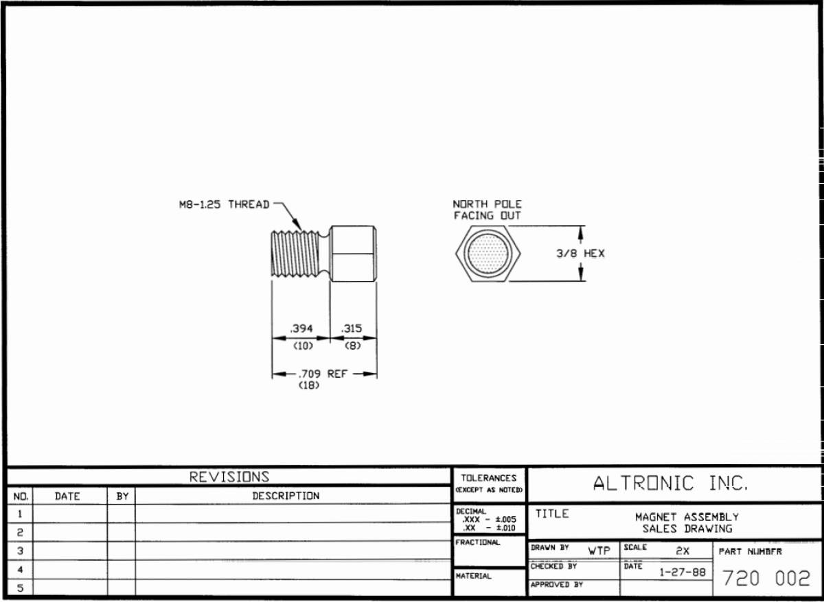
The trigger magnet (260604, 260605 or 720002) must be mounted on the engine camshaft or other accessory drive operating at camshaft speed. An M8 (8 mm) tapped hole, 0.5 inches (13 mm) deep is required – see drawings 260604, 260605 or 720002 for details. The magnet MUST rotate on a diameter NOT EXCEEDING: – 6 inches (150 mm) for magnet 720002, or – 15 inches (375 mm) for magnet 260604 or 260605.
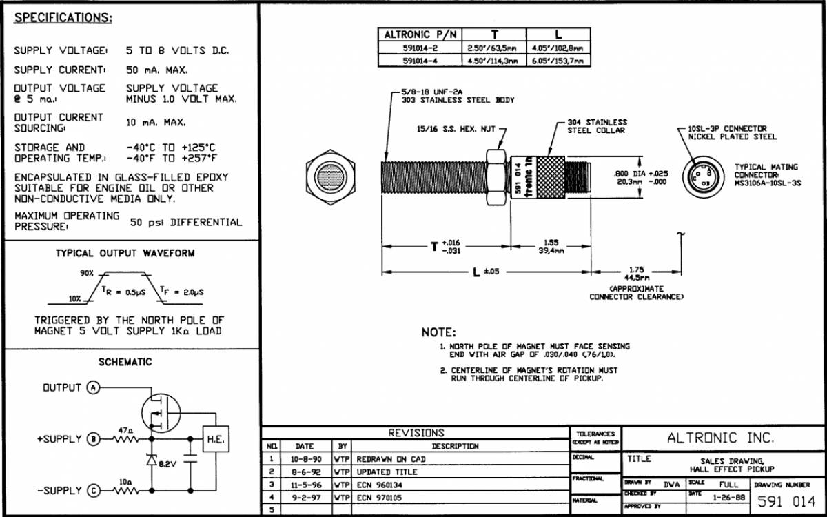
Set the engine on the COMPRESSION stroke of no. 1 cylinder with the reset pin DIRECTLY OPPOSITE the reset pickup. The Hall-effect pickup ( 591014-x) must be mounted DIRECTLY OPPOSITE the trigger magnet (section 8.1) coincident with the reset pickup and pin being lined-up – refer to drawing 209 060A. NOTE: The Hall-effect signal and the reset pickup signal must occur at the same time for the system to function. The Hall-effect pickup dimensions are shown on drawing 591 014. The air gap between the Hall-effect pickup and trigger magnet must not exceed .040” (1.0mm).
LOGIC MODULE ELECTRICAL HOOK-UP
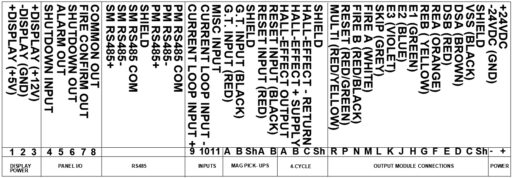
NOTE: When replacing an existing CPU-2000 Logic Module, all connectors can be directly connected. However, for modbus communication the Diagnostic module modbus wires must be moved to the PM 485 inputs. Customer modbus connections will connect to the SM 485 inputs.
The power connections to the NGI-5000 Legacy Logic Module must be in accordance with the National Electrical Code or other applicable country code. The NGI-5000 Logic Module is suitable for installation in Class I, Division 2, Group D locations.
The Logic Module must have its own 24 Vdc power connection. An external fuse near the power source is recommended for a power consumption of up to 5A max. See section 13.0 for other details regarding powering the CPU-2000 system.
Power wiring and signal (transducers) wiring must be in separate conduits and conduit entries into the Logic Module to avoid undesired electrical interaction. All conduit entries are sized for a 1 /2“-14 NPT male conduit fitting. Separate as follows (refer to drawing no. 209 078): RIGHT CONDUIT ENTRY Power wiring and cable 293030-xx to Diagnostic or Output Module CENTER CONDUIT ENTRY Magnetic pickups and Hall-effect pickup LEFT CONDUIT ENTRY Control inputs, serial communications, and alarm outputs
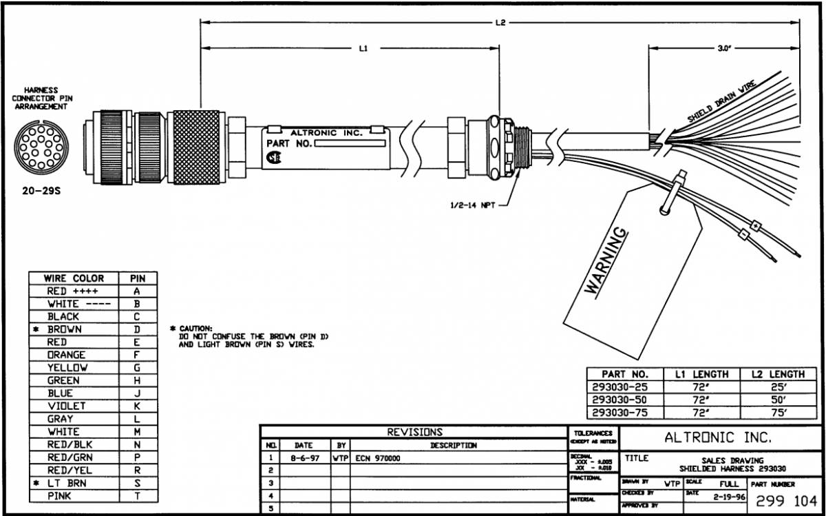
RIGHT ENTRY: Input power supply wires (16 AWG minimum) should enter the right conduit entry and connect to the 24 Vdc supply terminals of terminal block. The interface cable 293030-xx connecting the Logic Module with eitherthe Diagnostic or Output Module also enters through the right conduit entry. Refer to drawings 209078 and 299 104 for connection details. CAUTION: Do not mistake the brown (pin “D”) and light brown (pin “S”) wires.
Run a separate conduit for the two (2) magnetic pickup cable assemblies. These should enter through the center entry in the CPU box and terminate as shown on drawing 209 078. 4-CYCLE ENGINE ONLY: The cable from the Hall-effect pickup also enters through the center entry and connects as shown.
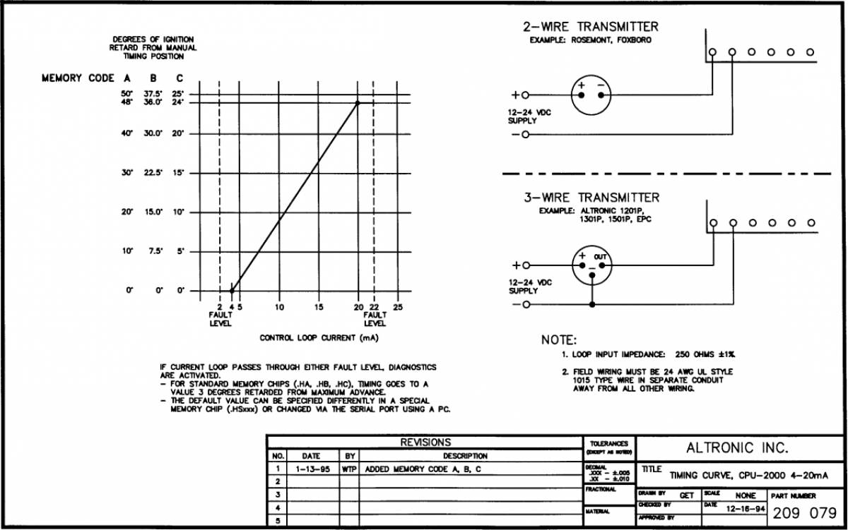
LEFT ENTRY: A separate conduit must be used to the left-hand entry for all connections to the user interface terminal strips in the Logic Module. Use 24 AWG, UL style 1015 wire or shielded cable for these connections; the 24 AWG wire is available from Altronic under part no. 603102 (black) or 603103 (white). A. SHUTDOWN INPUT (terminal 4): Use to stop the ignition for engine shutdown. This input is open for normal operation of the system and is connected to engine ground to inhibit ignition firings. NOTE: This is a 5 volt low level signal. B. ALARM OUT (terminal 5), SHUTDOWN OUT (terminal 6), FIRE CONFIRM OUT (terminal 7): Three output switches are available for monitoring ignition system status. Each output consists of a solid state switch normally closed to a single common rail COMMON OUT (terminal 8). The switches are rated 75 mA@ 100 Vdc. These output switches are electrically isolated from all other terminals. The recommended hook-up is shown on drawing 209078. For operational details, refer to the CPU-2000 Operating Instructions, form CPU-2000 01. C. 4-20 MA TIMING CONTROL INPUT: The 4-20 mA timing control loop connects to terminals 9( +) and 10(-). This input is electrically isolated from all other terminals; refer to drawings 209078 and 209 079. D. MISC INPUT (terminal 11): Provides for control of various user selected features. This input is normally open; connect to engine ground to activate the selected feature (see drawing 209 078). NOTE: This is a 5 volt low level signal. For programming and operational details, refer to CPU-2000 Operating Instructions, form CPU-2000 01.
DC POWER HOOKUP -293030-XX: CABLE
The power connections to the CPU-2000 must be in accordance with the National Electrical Code or other applicable country code. The CPU-2000 is suitable for installation in Class I, Division 2, Group D locations.
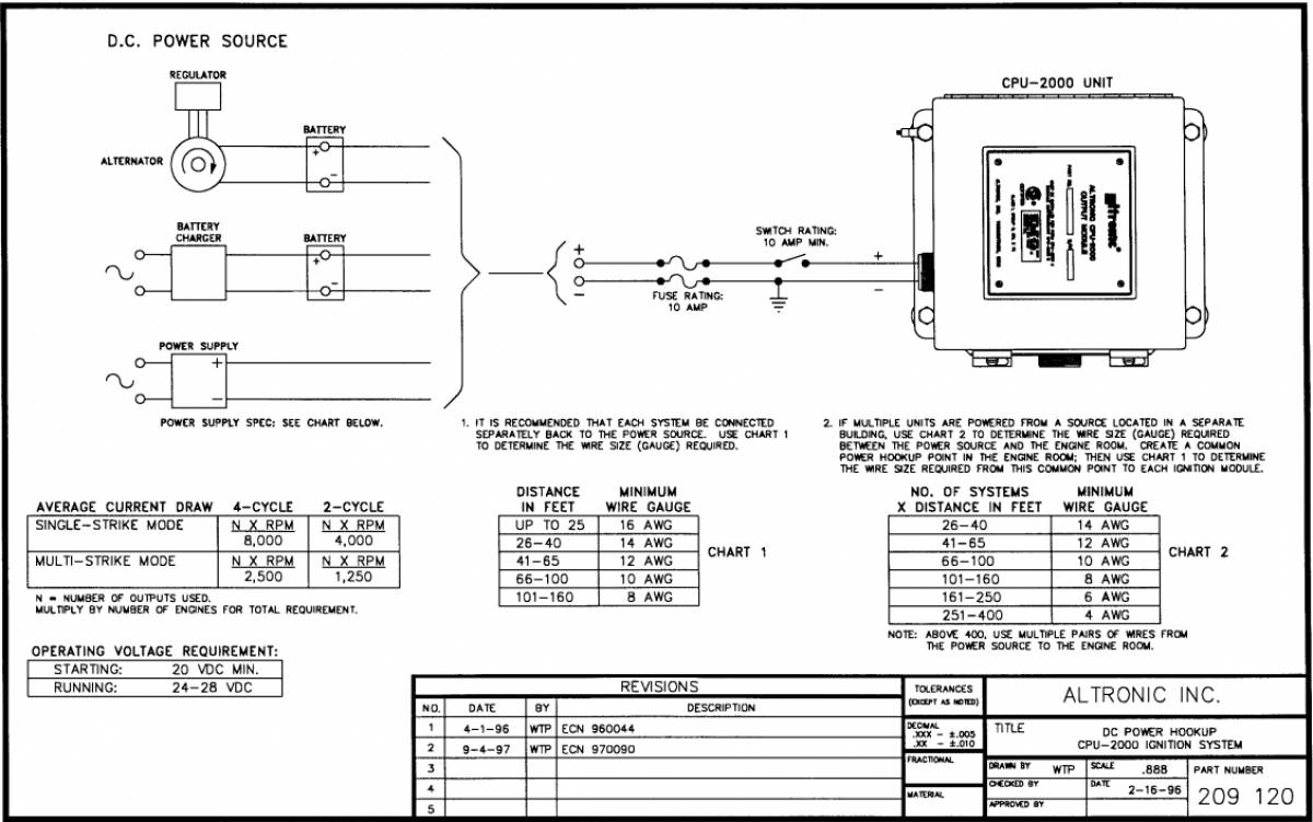
It is necessary to split the control cable and power leads of the 293030 cable in an engine mounted junction box or conduit tee. This box should be separate from the main junction box used to terminate the output harness(es) to the ignition coils. The junction box should have three (3) 1/2” conduit entries (refer to drawing 209 077 or 209 077A): 1 ST ENTRY – Conduit fitting of 293030 series connecting cable from the Output Module. 2ND ENTRY – Two leads from a source of nominal 24 Vdc (20-32 Vdc). The negative of the 24 Vdc supply MUST be common with engine ground. Refer to drawing 209 120 for details of the power hookup. 3RD ENTRY – The gray jacketed control cable from the 293030 series cable connecting to either the Diagnostic or Logic Module.
The CPU-2000 system can be powered in one of the following ways: A. 24 volt battery with charger. B. DC power supply capable of furnishing 24-28 Vdc. NOTE: The negative (-) of the 24 Vdc supply MUST BE COMMON WITH ENGINE GROUND. Engines using positive ground DC accessories or starter motors will require a separate dedicated power supply for the CPU-2000.
IMPORTANT: For proper operation of the CPU-2000 system, voltage and current supplied must be sufficient during all selected modes of operation. Drawing 209 120 provides these details regarding the DC power hook-up: 1. CURRENT DRAW PER SYSTEM – formula varies depending on number of outputs used, engine cycle and RPM, and the use of the multi-strike feature. 2. MINIMUM WIRE GAUGE REQUIREMENTS – Chart 1 of drawing 209120 gives the requirement vs. the length of run between the power source and the CPU-2000 Output Module. 3. MULTIPLE ENGINE INSTALLATIONS – Multiply current required per system by the number of engines. Where more than one engine is powered from a common power source, see Chart 2 of drawing 209120 for the minimum wire size required.
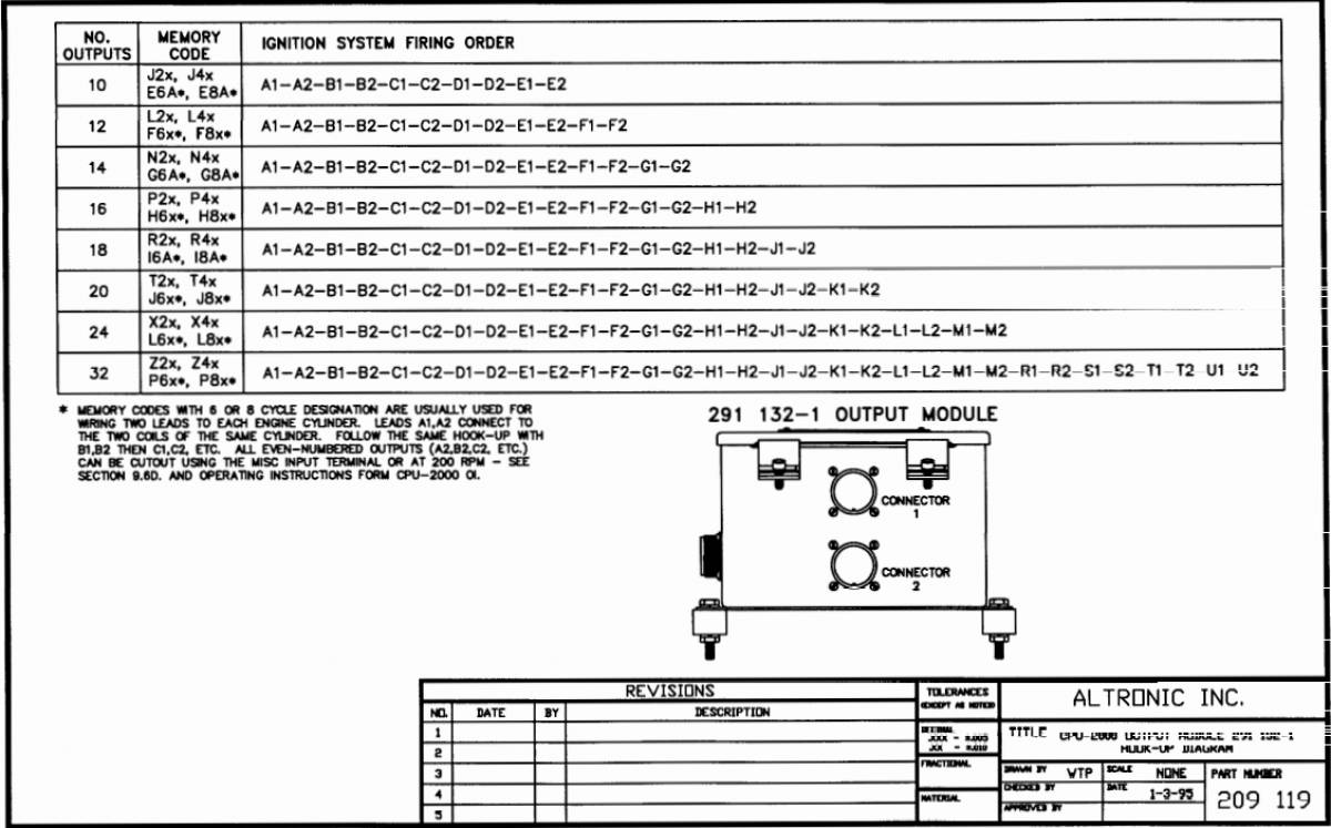
PRIMARY WIRING
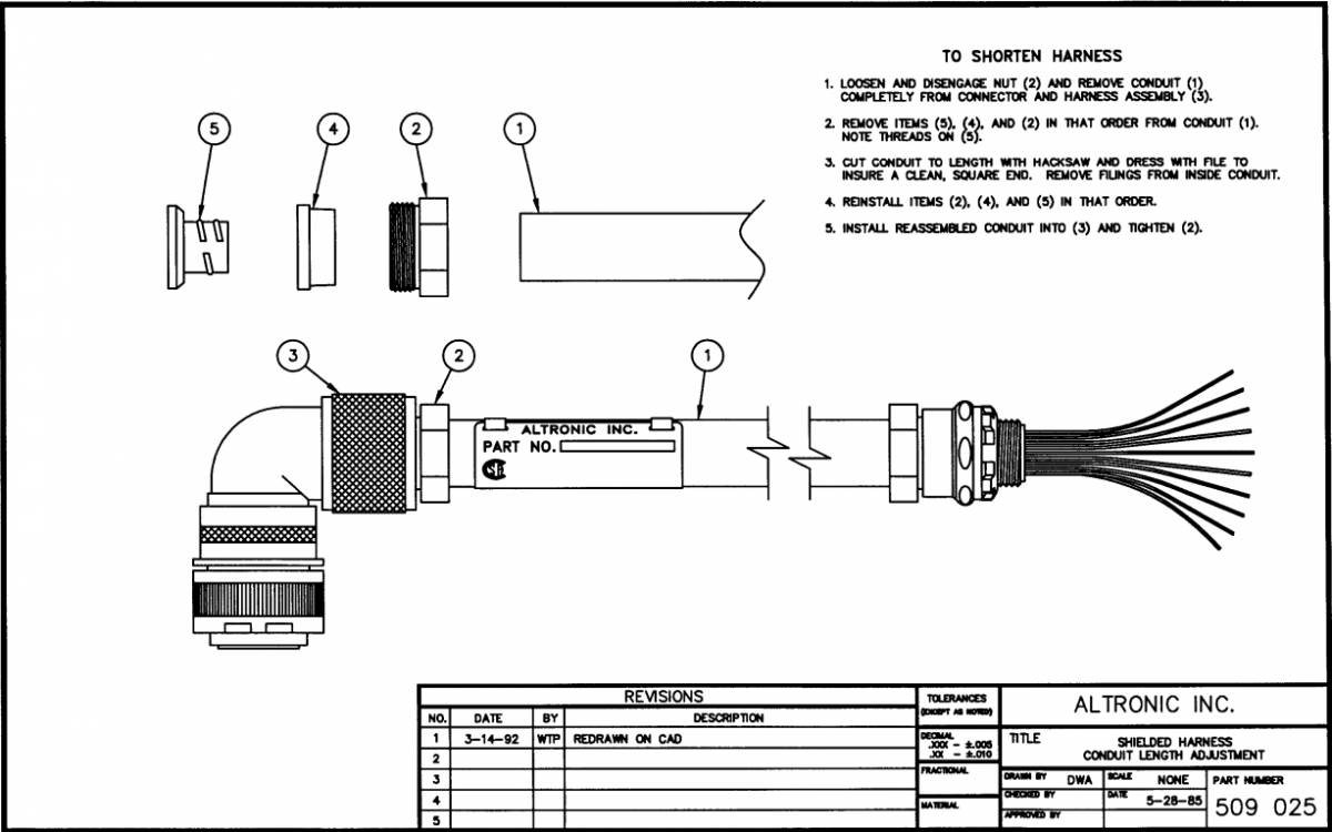
The main wiring harness (293023-x, 293026-x, or 293027-x) connects the Output Module to the engine junction box. Refer to drawing 509025 if it is desired to shorten the conduit length of the harness. Insert the connector into the Altronic CPU-2000 Output Module receptacle and tighten hand-tight; then carefully tighten an additional one-sixth turn with a wrench. NOTE: Two harnesses are used with Output Module type 291 132-1. Referring to applicable drawing 209 118 or 209 119, write in the engine firing order below:
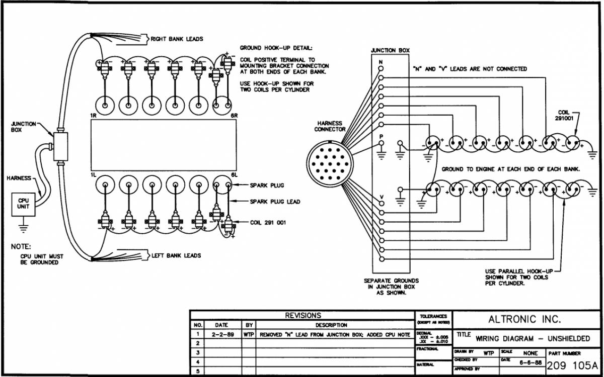
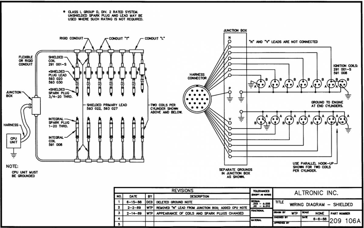
Connect the harness leads in the junction box in accordance with the engine’s firing order. The leads from the junction box corresponding to the above system outputs connect to the ignition coil negative(-) terminals. The “P” lead and the common coil ground lead(s) connecting the positive ( +) terminals of the ignition coils must be grounded to the engine in the junction box. On V-engines, run a separate common ground lead for each bank. Separate ground connections in the junction box are recommended. Refer to wiring diagrams 209105A (unshielded) or 209106A (shielded) for general details.
Primary wire should be no. 16 gauge stranded, tinned copper wire. The insulation should have a minimum thickness of .016“ and be rated 105°C. or higher. Irradiated PVC or polyolefin insulations are recommended. Altronic primary wire no. 503188 meets these specifications. All primary wiring should be protected from physical damage and vibration.
If two ignition coils per cylinder connected to a common output are used, use PARALLEL WIRING as shown on the wiring diagrams 209105A and 209106A.
All unused primary wires should be individually taped so that they are insulated from ground and each other. The unused primary wires can then be tie-wrapped together for a clean installation.
SHUTDOWN WIRING
To shut-off the DC-powered CPU-2000 system, a special input (SHUTDOWN INPUT – terminal 4) in the Logic Module is provided. This input is open for normal operation and is connected to engine ground to initiate an ignition shutdown. Use a switch rated 24 Vdc, 0.5 amps. Refer to section 9.6A. and drawing 209078 for details.
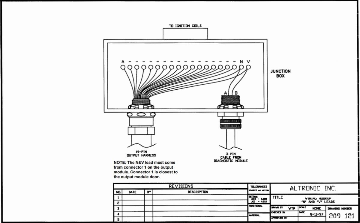
DO NOT ground leads “N” or “V” to stop the ignition with the CPU-2000 system. This can cause component failure in the Output Module. These leads are provided to power existing ignition powered instruments and for scope analysis only.
SECONDARY WIRING
Mount the ignition coils as close as possible to the engine spark plugs consistent with a secure mounting and avoidance of temperatures in excess of 185°F (85°C.).
The spark plug leads should be fabricated from silicone insulated 7 mm cable with suitable terminals and silicone spark plug boots. The use of leads with resistor spark plug boots (Altronic series 59320x-xx) is recommended to minimize interference from emitted RFI on the operation of other nearby electronic equipment. Another option is the use of suppression ignition cable (Altronic part no. 503185). It is also essential to keep spark plug leads as short as possible and in all cases not longer than 24 inches (600 mm). Spark plug leads should be kept at least 2 inches (50 mm) away from any grounded engine part. In deep spark plug wells, use rigid insulated extenders projecting out of the well.
The use of a clear, silicone grease (such as Dow Corning DC-4, G.E. G-623 or GC Electronics ZS) is recommended for all high-tension connections and boots. This material helps seal out moisture and prevent corrosion from atmospheric sources.
Figures
Wiring Diagram
Timing Curve
Pickup Mounting
Flywheel Hole Drilling
Wiring Diagram Unshielded
Wiring Diagram Shielded
Hookup Diagram Dual Output
Power Hookup
Wiring Hookup N and V
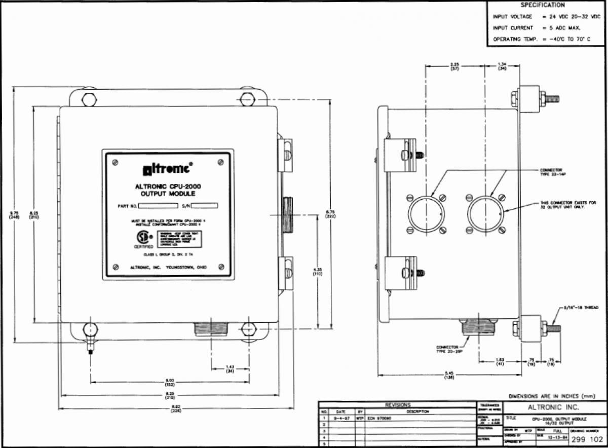
Output Module Dimensions
Diagnostic Module Dimensions
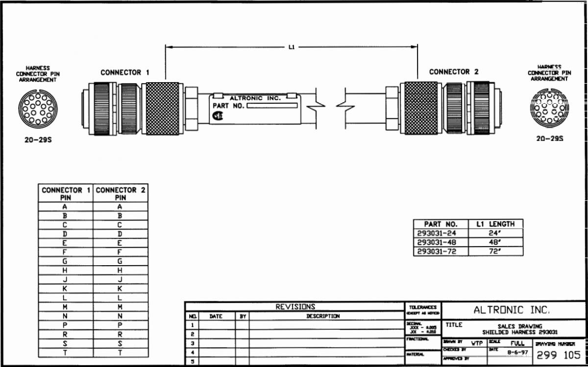
Shielded Harness
Shielded Harness
Conduit Length Adjustment
Magnet Holder
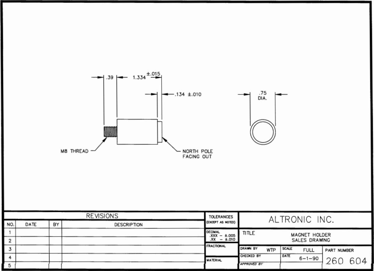
Magnet Holder Dimensions
Magnet Assembly
Hall Effect Pickup Dimensions
Magnetic Pickup Dimensions