SYSTEM OVERVIEW
Logic modules with software version 2.0 or greater have the ability to select between Legacy mode, which works with the existing CPU-2000 system or NGI-5000 full system mode which works in conjunction with CIU’s, DCPM, and NGI-5000 coils. Switching between the two modes is accomplished by using the engine configuration tool and selecting the type of system installed. Once configured the appropriate screens will be displayed, and the proper diagnostic functions will be enabled.
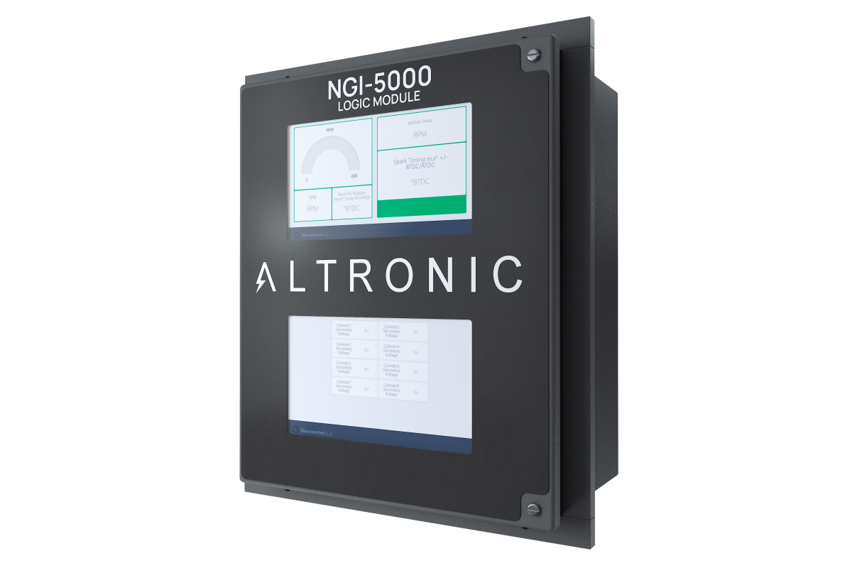
The NGI-5000 Logic Module Legacy Mode is designed to be a drop in replacement. While the screens are different and updated, the functions and set up of the system should be familiar. Benefits to the new logic module offer increased availability of information using high resolution LCD screens, upgraded EEPROM storage, web based technology for viewing with no proprietary downloaded tools, state of the art computing power, and flexibility for future applications.
LOGIC MODULE USER INTERFACE
Using the logic module consists of two screens on the module, top for quick view, bottom for dynamic viewing, and the ability to log into the unit with any ethernet based host device such as a PC. All technology being viewed is browser based and therefore needs no proprietary installation of tools. It also allows for configurability of the screens for external viewing and launching a new view on the top and bottom module screens.
A customer based ethernet port is available inside the NGI-5000 logic module. Open the enclosure door use the port that is in the lower left corner labeled eth 0.
Viewing the NGI-5000 Logic Module with an AWI on an external device is available using the AWI tool, IP address 192.168.1.2:8080
Accessing the Engine Configuration Tool while connected to the customer ethernet port is available at IP address 192.168.1.2 notice there is no port 3000 at the end.
Click here for AWI CONNECTION AND INTERFACE MANUAL for information on configuring your host device with the correct port setting to be able to interface with the NGI-5000 logic module
DESCRIPTION OF OUTPUT SWITCHES
Three output switches provide a means of communicating the current ignition status to other systems. These switches have isolated outputs and share one common return path which is not referenced to engine or power ground. They will be in the open condition when the unit is unpowered. A typical application would be as a relay or solenoid coil driver. – The FIRE-CONFIRM OUT switch is closed to signal that the ignition is running with no faults or ignition warnings. Warnings identified by the Diagnostic Module do not effect this output. Note: Switch is not opened for warnings with firmware version 2.1. – The SHUTDOWN OUT switch is closed to signal that the ignition has detected no faults which would result in a self shutdown. Upon detecting a fault that would result in a selfshutdown of the ignition, this switch will open. – The ALARM OUT switch is closed to signal that no un-acknowledged faults or warnings are present. Upon detection of a fault, ignition warning or a diagnostic warning, this switch will open. This output is designed to control an alarm indicator or sounding device.
UNDERSTANDING THE HOME SCREEN
TOP SCREEN CPU-2000 VERSION
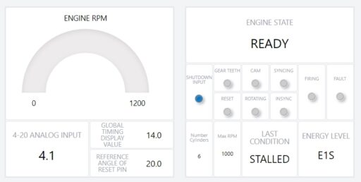
A top screen is for a view of information and can be changed if other quick view information is desired.
ENGINE STATE is the the current state of the NGI-5000 in it’s operation
Following the ENGINE STATE are state input LEDs. Therefore it is aiding the user in a two staged approach to understand what is happening within the NGI-5000 Logic. The state input LEDs move through their logic, illuminate and turn off depending on their status.
For Example if the ENGINE STATE says rotating, all of the pick-ups are on, INSYNC is on, and shutdown is on the ignition is in the rotating state and capable of firing but the shutdown input is engaged.
LAST CONDITION is intended to notify the user of what happened in the engine state as a result of shutting down. It is persistent as long as power is applied.
ANALOG INPUT indicates the input in mA of the 4-20mA signal
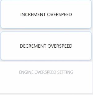
Other visualization items include the programmed number of cylinders, overspeed setting, current energy level, and global timing
BOTTOM SCREEN CPU-2000 VERSION
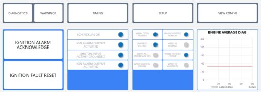
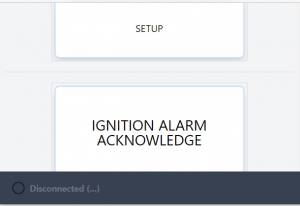
Interfacing with the bottom screen is dynamic with a touch interface. Buttons are available to open additional windows, and to activate different features, as well as the ability to scroll on the screen.
Click Diagnostics to show available diagnostics from the Diagnostic Module.
Click Warnings to show available warnings from the Diagnostic Module.
Click Setup to adjust ignition and diagnostic parameters
Click Timing to adjust parameters related to spark timing
Click View Config to see a read only view of how the ignition is configured for the engine parameters
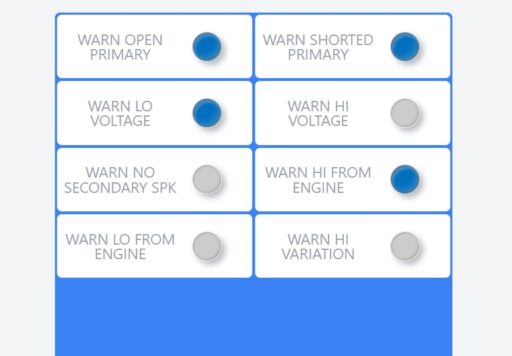
Global warnings that are tripped from diagnostic module; go to Warning button to view individual warnings; go to Diagnostics button to view individual cylinder diagnostic values
CLOSING ADDITIONAL SCREENS
Clicking on the Diagnostic, Timing, or Setup buttons open up new screen that allow for viewing and interaction for its specific functions. With every window that opens a close out “X” will be in the upper right hand corner.

ADJUSTING GLOBAL RETARD
Global retard is an adjustment affecting the timing of all cylinders equally. This adjustment can be equated to the manual timing switch of the Altronic II-CPU system. Adjustments made as described below will be in effect until another adjustment is made.
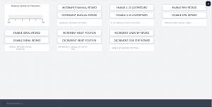
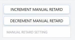
Adjustment of the manual retard in 1 degree and .1 degree increments
SELECTION OF GLOABL TIMING MODES
Several options exist with regard to global timing modes. Once the global timing mode menu is entered as described below, the status of each option can be viewed and changed.
Selection can enable or disable the pre-configured retard curve controlled internally by engine RPM.

Selection can enable or disable the pre-configured retard curve controlled by the 4-20 mA current loop input. The choices are ON and OFF,
SETUP CONTROL OPTIONS
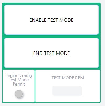
Test mode must be enabled in the engine configuration first, then it can be turned on. Enter the RPM desired for test mode to operate at and press enable test mode.
NGI-5000 DIAGNOSTICS CPU-2000 VERSION
UNDERSTANDING AND USING THE SECONDARY SPARK DIAGNOSTICS
The spark reference number is a unit less number which correlates with voltage demand at the spark plug and is calculated for every firing of each cylinder. As the voltage increases, the reference number also increases. The number is non-linear and will increase faster at higher voltages (above 20kV). The usefulness of the number lies not in its absolute value, but rather in how the number changes over time as the spark plugs erode. With a little experience, the engine operator will be able to tell when spark plugs require changing. Abnormal conditions in the ignition system, such as open or short circuits in the primary and secondary wiring, can also be detected.
The following spark reference numbers are available in the CPU-2000 system: INSTANTANEOUS (INST): The numbers read back from the system in real time. VARIATION (COV): The variation in values for the cylinder being viewed. CYL. AVERAGE (CAVG): The average value for the cylinder being viewed. MINIMUM VALUE (MIN): The minimum CAVG value since the last time reset. MAXIMUM VALUE (MAX): The maximum CAVG value since the last time reset. NOTE: The above values are available on a per cylinder (or per coil/spark plug) basis. ENG. AVERAGE (EAVG): The average value for all cylinders of the engine. or GROUP AVERAGE (1AVG): The average value for all outputs of connector group 1. GROUP AVERAGE (2AVG): The average value for all outputs of connector group 2. NOTE: The (EAVG) average value indicates the average conditions of the entire engine.
The spark reference number will have a characteristic range depending on the type of coil used. There are known differences between the various types of Altronic coils, and slight variations are normal between coils of the same type. In order to maximize the usefulness of the cylinder spark reference number, it is recommended that all coils be of the same type and vintage (production date). The typical ranges to be expected in normal operation with new spark plugs are:
In addition to the diagnostic flags, the spark reference numbers can also be used for predictive purposes: A. As the numbers increase toward the preset HI SPARK VOLTAGE threshold the operator knows that a change of spark plugs should be scheduled. With this information, spark plug replacement can be determined on an actual need basis rather than a predetermined schedule. Also, unexpected engine misfiring or shutdowns can be avoided by tracking the reference numbers on a routine basis. B. The reference numbers can provide an early warning of a difference in operation in a given cylinder(s). A reading higher or lower than other cylinder tells the operator of a potential problem. This allows further troubleshooting and evaluation to take place before an unexpected operational problem develops.
The spark energy setting has only a small effect on the spark reference number if the spark plug fires correctly. Therefore, the high and low voltage thresholds should hold across energy setting changes if the spark plugs continue to fire normally. On the other hand, a worn plug may not fire consistently on energy setting E1 but will on energy setting E2; in this case there will be a significant difference in the reference number when the energy setting is changed.
Operators may be able to increase spark plug life by using the automatic energy adjustment feature of the CPU-2000 system. In this mode, the system uses the spark reference numbers to establish the lowest required energy level to minimize spark plug erosion rates. To use this feature, the basic setup energy should be set to E1.
The secondary spark diagnostics will operate with either one or two coils connected to each system output lead. Optimum operation is obtained when only one coil is connected to each output lead; in this case, only one spark plug condition effects the spark reference number for that output. When two coils are wired in parallel to a common output lead, the spark reference number will tend to be an average of the condition at the two spark plugs. While deviations between cylinders will be somewhat harder to detect, most of the benefits of the spark reference number can still be realized.
Updating Firmware and Software
It is important to note, that the ST firmware should be updated first, followed by the CM4 computer module.
This is a two step process. with two different targets. The ST microcontroller which takes firmware in a .bin file. Then a CM4 computer module software update which requires a very specific process using a zip file. It is important to follow the instructions below in detail.
The two devices ( ST microcontroller and CM4 computer module) talk to each other and must stay in sync. Therefore it is imperative to match the Firmware and Software files and that they update correctly. If one of the devices do not match the other they can not talk and the screens will show disconnected.
Transferring Firmware to ignition ST microcontroller
OVERVIEW
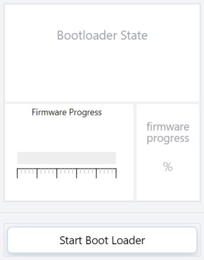
To perform all of the position sensing, and ignition coil fire output sequencing there is an embedded microcontroller. A USB drive can be installed into the logic module. Then through the “view config” menu a process can be initiated to send new firmware to the embedded ST micro. A status indication and percentage meter are visible for feedback. During the process it is critical not to interrupt power or the device can become corrupted and special tools would be required to recover the device.
Firmware preparation
A firmware file from altronic is required to perform the update. It will come as a .bin file and can be found at the following link https://github.com/Altronic-LLC/Altronic-Public-Files/tree/main/NGI-5000-Software/ST-Firmware
Once the firmware file has been downloaded, it must be unzipped on your personal PC. Place a single unzipped .bin file in the top directory of a thumbdrive. It is important to pay attention that there is only this one .bin file on the thumb drive and it is not in any folders.
For earlier versions of the NGI-5000 Logic Module (1.4 and below) it is important to rename the .bin file exactly as stated below:
NGI-5000-CRC
This will insure that the NGI-5000 will find the file name and allow you to install. We are working to integrate the entire process into one on future versions.
USB installation
Take the USB drive with only one .bin file at the root of the drive, and install it in the right side USB A input connector.
Initiating the firmware update
Navigate on the display of the logic module to the view config button and press it. Then scroll to the bottom of the page.
With the USB drive inserted, click start bootloader. The progress will start to increase. Once it reaches 100% the state will go to done. After the status says done, scroll to the top of the page and the firmware date should now read the date that was on the .bin file name.
If you receiver “Error” in the Bootloader state, the most likely cause is an incorrect file name. Insure the file name is exactly as above with all capital letters.
Transferring software to the CM4 computer module
Overview
All current releases of the CM4 updater process requires the use of a keyboard and the ability to exit the kiosk view of the product. This can be done by plugging in a combination keyboard and touch pad into the USB port on the Logic Module. A .zip file is provided, and like a standard computer, the .zip file is moved to the desktop. It must be unzipped, and then a file is double clicked to run. The unit will reboot itself and a new readme file is installed on the desktop. Inside the Readme file is a new date and version to verify the update was successful.
Software Preparation
A software file from altronic is required to perform the update. It will come as a .zip file and can be found at the following link https://github.com/Altronic-LLC/Altronic-Public-Files/tree/main/NGI-5000-Software/CM4-Update
Unlike the ST firmware, the CM4 updater must be left in a zipped state and placed on a thumbdrive. This can then be used to transfer to the NGI-5000 Logic module.
USB installation
Take the USB drive with only one .zip file at the root of the drive, and install it in the right side USB A input connector.
Updater Process
With a keyboard installed into a USB port (this may require the touchscreen to be disconnected to free up a port) or you can use a USB hub, press and hold
Alt + press F4. This will have to be done twice to close both kiosk screens]
Find the folder icon at the top, then open the USB thumbdrive installed with the .zip file.
Copy the zip file from the thumbdrive and move it onto the desktop.
Right click the .zip file on the desktop and click extract here
A folder will now be on the desktop with the name of the software version that you downloaded
Double click the folder on the desktop and double click the .sh file.
A window will pop up, click “execute”.
This has now initiated the upload process. It takes about 30 sec to a minute to update.
There will be a prompt on the screen that shows the progress and when complete will ask to press any key to reboot the system.
You can then perform the ALT+F4 operation to get back to the desktop and look at the readme for the correct date and version.
When the system reboots, the NGI-5000 screens will come back and should show connected. Going to the config screen will show the date of the ST firmware for verification.
Performing the Alt+F4 operation will bring you back to the desktop view and a readme file is located there. Double clicking that will bring up a text file in an editor. On the main section of the screen will be lines of text describing the file version and date. This will tell you what version of the CM4 computer software is installed.
NOTE: If the release notes mention any updates to the engine configuration tool, it is recommended to redo the engine configuration and export a new JSON. There are dates in the config tool that allow you to see if there are changes to the tool as well and what version of JSON was exported. While we strive to not make breaking changes and maintain compatibility, some of these are unavoidable.
Communications
The NGI-5000 Logic module supports 2-wire RS485 Communications:
Connect to terminals PM(+) and PM(-)
9600 Baud, None, 1
10000 Logic Module Registers
| 1 | IGN SHUTDOWN FLAG | SHUTDWNFLGBOOL | ReadOnly | BOOL |
| 2 | IGN WARNING FLAG | WARNINGFLGBOOL | ReadOnly | BOOL |
| 3 | IGN FAULT FLAG | FAULTFLGBOOL | ReadOnly | BOOL |
| 4 | IGN FIRED FLAG | FIREDFLGBOOL | ReadOnly | BOOL |
| 5 | IGN ALARM OUTPUT ACTIVATED | ALRMOUTBOOL | ReadOnly | BOOL |
| 6 | IGN FIRING FLAG | FIRINGFLGBOOL | ReadOnly | BOOL |
| 7 | IGN PICKUPS OK | PICKUPSOKBOOL | ReadOnly | BOOL |
| 8 | IGN ENGINE ROTATING | ENGNROTBOOL | ReadOnly | BOOL |
| 9 | SHUTDN INPUT 1=ACTIVE=GROUNDED | SHUTDWNINBOOL | ReadOnly | BOOL |
| 10 | BANK CUTOFF ON NOW | spare100010 | ReadOnly | BOOL |
| 11 | MISC. INPUT 1=ACTIVE=GROUNDED | spare100011 | ReadOnly | BOOL |
| 12 | ONE STEP ACTIVE NOW | spare100012 | ReadOnly | BOOL |
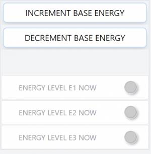
| 13 | ENERGY LEVEL E1 NOW | ENRGLVLE1 | ReadOnly | BOOL |
| 14 | ENERGY LEVEL E2 NOW | ENRGLVLE2 | ReadOnly | BOOL |
| 15 | ENERGY LEVEL E3 NOW | ENRGLVLE3 | ReadOnly | BOOL |
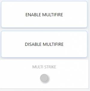
| 16 | MULTI STRIKE NOW | MULTISTRKNOW | ReadOnly | BOOL |
| 17 | FAULT NO GEAR TOOTH SIGNAL | FLTNOGT | ReadOnly | BOOL |
| 18 | FAULT NO RESET SIGNAL | FLTNORESET | ReadOnly | BOOL |
| 19 | FAULT NO HE CYCLE SIGNAL | FLTNOHE | ReadOnly | BOOL |
| 20 | FAULT WRONG NUMBER OF TEETH | FAULTTEETH | ReadOnly | BOOL |
| 21 | FAULT OVERSPEED SHUTDOWN | FLTOVRSPD | ReadOnly | BOOL |
| 22 | FAULT MISALIGNED CAM | FLTMISLNDCAM | ReadOnly | BOOL |
| 23 | spare | spare100023 | ||
| 24 | FAULT FIRMWARE CHECKSUM ERR | FLTFRIMWARECHKSUM | ReadOnly | BOOL |
| 25 | WARN LOW VOLTAGE BANK A | WARNLOWVOLTA | ReadOnly | BOOL |
| 26 | WARN LOW VOLTAGE BANK B | WARNLOWVOLTB | ReadOnly | BOOL |
| 27 | WARN NO DISCHARGE ON BANK A | WARNNODSCHBNKA | ReadOnly | BOOL |
| 28 | WARN NO DISCHARGE ON BANK B | WARNNODSCHBNKB | ReadOnly | BOOL |
| 29 | WARN 4-20 LOOP OUT OF RANG | WARN420LOOP | ReadOnly | BOOL |
| 30 | WARN FAIL TO DETECT DIAG UNIT | WARNNODIAGUNIT | ReadOnly | BOOL |
| 31 | WARN EEPROM CHECKSUM FAIL | WARNEECHKSUM | ReadOnly | BOOL |
| 32 | WARN FAIL DETECT DISP BOARD | WARNNODISPLAY | ReadOnly | BOOL |
| 33 | WARN NO DISCHARGE ON *C1* (A or A1) | WARNNODSCHRGA | ReadOnly | BOOL |
| 34 | WARN NO DISCHARGE ON *C3* (C or B1) | WARNNODSCHRGC | ReadOnly | BOOL |
| 35 | WARN NO DISCHARGE ON *C5* (E or C1) | WARNNODSCHRGE | ReadOnly | BOOL |
| 36 | WARN NO DISCHARGE ON *C7* (G or D1) | WARNNODSCHRGG | ReadOnly | BOOL |
| 37 | WARN NO DISCHARGE ON *C9* (J or E1) | WARNNODSCHRGJ | ReadOnly | BOOL |
| 38 | WARN NO DISCHARGE ON *C11* (L or F1) | WARNNODSCHRGL | ReadOnly | BOOL |
| 39 | WARN NO DISCHARGE ON *C13* (R or G1) | WARNNODSCHRGR | ReadOnly | BOOL |
| 40 | WARN NO DISCHARGE ON *C15* (T or H1) | WARNNODSCHRGT | ReadOnly | BOOL |
| 41 | WARN NO DISCHARGE ON *C17* ( J1) | WARNNODSCHRGJ1 | ReadOnly | BOOL |
| 42 | WARN NO DISCHARGE ON *C19* ( K1) | WARNNODSCHRGK1 | ReadOnly | BOOL |
| 43 | WARN NO DISCHARGE ON *C21* ( L1) | WARNNODSCHRGL1 | ReadOnly | BOOL |
| 44 | WARN NO DISCHARGE ON *C23* ( M1) | WARNNODSCHRGM1 | ReadOnly | BOOL |
| 45 | WARN NO DISCHARGE ON *C25* ( R1) | WARNNODSCHRGR1 | ReadOnly | BOOL |
| 46 | WARN NO DISCHARGE ON *C27* ( S1) | WARNNODSCHRGS1 | ReadOnly | BOOL |
| 47 | WARN NO DISCHARGE ON *C29* ( T1) | WARNNODSCHRGT1 | ReadOnly | BOOL |
| 48 | WARN NO DISCHARGE ON *C31* ( U1) | WARNNODSCHRGU1 | ReadOnly | BOOL |
| 49 | WARN NO DISCHARGE ON *C2* (B or A2) | WARNNODSCHRGB | ReadOnly | BOOL |
| 50 | WARN NO DISCHARGE ON *C4* (D or B2) | WARNNODSCHRGD | ReadOnly | BOOL |
| 51 | WARN NO DISCHARGE ON *C6* (F or C2) | WARNNODSCHRGF | ReadOnly | BOOL |
| 52 | WARN NO DISCHARGE ON *C8* (H or D2) | WARNNODSCHRGH | ReadOnly | BOOL |
| 53 | WARN NO DISCHARGE ON *C10* (K or E2) | WARNNODSCHRGK | ReadOnly | BOOL |
| 54 | WARN NO DISCHARGE ON *C12* (M or F2) | WARNNODSCHRGM | ReadOnly | BOOL |
| 55 | WARN NO DISCHARGE ON *C14* (S or G2) | WARNNODSCHRGS | ReadOnly | BOOL |
| 56 | WARN NO DISCHARGE ON *C16* (U or H2) | WARNNODSCHRGU | ReadOnly | BOOL |
| 57 | WARN NO DISCHARGE ON *C18* ( J2) | WARNNODSCHRGJ2 | ReadOnly | BOOL |
| 58 | WARN NO DISCHARGE ON *C20* ( K2) | WARNNODSCHRGK2 | ReadOnly | BOOL |
| 59 | WARN NO DISCHARGE ON *C22* ( L2) | WARNNODSCHRGL2 | ReadOnly | BOOL |
| 60 | WARN NO DISCHARGE ON *C24* ( M2) | WARNNODSCHRGM2 | ReadOnly | BOOL |
| 61 | WARN NO DISCHARGE ON *C26* ( R2) | WARNNODSCHRGR2 | ReadOnly | BOOL |
| 62 | WARN NO DISCHARGE ON *C28* ( S2) | WARNNODSCHRGS2 | ReadOnly | BOOL |
| 63 | WARN NO DISCHARGE ON *C30* ( T2) | WARNNODSCHRGT2 | ReadOnly | BOOL |
| 64 | WARN NO DISCHARGE ON *C32* ( U2) | WARNNODSCHRGU2 | ReadOnly | BOOL |
| 65 | PROTECTION ENABLED EEPROM | PROTECTEEPROM | ReadOnly | BOOL |
| 66 | SERIAL RETARD ENABLED EEPROM | SERIALRTD | ReadOnly | BOOL |
| 67 | RPM RETARD MAP ENABLED EEPROM | RPMMAP | ReadOnly | BOOL |
| 68 | 4-20ma RET MAP ENABLED EEPROM | MAP420 | ReadOnly | BOOL |
| 69 | BASE ENERGY E1 SELECT EEPROM | ENERGYE1 | ReadOnly | BOOL |
| 70 | BASE ENERGY E2 SELECT EEPROM | ENERGYE2 | ReadOnly | BOOL |
| 71 | BASE ENERGY E3 SELECT EEPROM | ENERGYE3 | ReadOnly | BOOL |
| 72 | MULTI-STRIKE SELECT EEPROM | MULTISTRIKE | ReadOnly | BOOL |
| 73 | spare | spare100073 | ReadOnly | BOOL |
| 74 | spare | spare100074 | ReadOnly | BOOL |
| 75 | spare | spare100075 | ReadOnly | BOOL |
| 76 | spare | spare100076 | ReadOnly | BOOL |
| 77 | spare | spare100077 | ReadOnly | BOOL |
| 78 | FW 2000 PRESENT IN IGNITION | FW2KPRSNT | ReadOnly | BOOL |
| 79 | 2 OUTPUTS PER CYLINDER MODE | TWOOUTPCYL | ReadOnly | BOOL |
| 80 | 32 OUTPUT MODE (1=32, 0=16) | OUTMODE32 | ReadOnly | BOOL |
| 81 | DIAG MODULE DETECT TOGGLE BIT | DIAGDETECTTGGL | ReadOnly | BOOL |
| 82 | 1=REQUEST RESET OF MIN/MAX | REQRSTMINMAX | ReadOnly | BOOL |
| 83 | 1=REQUEST RESET OF ALARMS | REQRSTALRMS | ReadOnly | BOOL |
| 84 | 1=SELECT HI DIAG FREQUENCY | SELCTHIDIAGFREQ | ReadOnly | BOOL |
| 85 | 1=DIAG 2000 DETECTED BY IGN | DIAGDETECTED | ReadOnly | BOOL |
| 86 | 1=DIAG MODULE ENABLE REQUEST | DIAGENREQ | ReadOnly | BOOL |
| 87 | 1=RPM ABOVE MIN/MAX THRESHOLD | RPMABVMINMAX | ReadOnly | BOOL |
| 88 | 1=DIAG READY FROM IGNITION | DIAGRDY | ReadOnly | BOOL |
| 89 | DIAG MODULE DETECT REPLY BIT | DIAGDETECTRPLY | ReadOnly | BOOL |
| 90 | 1=RESET MIN MAX CONFIRM BIT | CONFMINMAXRST | ReadOnly | BOOL |
| 91 | 1=RESET ALARMS CONFIRM BIT | CONFALRMRST | ReadOnly | BOOL |
| 92 | 1=NEW DIAG ALARM DETECTED | NEWDIAGALRM | ReadOnly | BOOL |
| 93 | 1=DUAL BANK DIAGNOSTIC F/W | DUALBANKDIAGFW | ReadOnly | BOOL |
| 94 | 1=DIAG MODULE READY BIT | DIAGMODRDY | ReadOnly | BOOL |
| 95 | 1=FIRE OVERRUN FLAG A (NO RST) | spare100095 | ReadOnly | BOOL |
| 96 | 1=FIRE OVERRUN FLAG B (NO RST) | spare100096 | ReadOnly | BOOL |
| 97 | WARN OPEN PRIMARY (global) | WARNOPENPRI | ReadOnly | BOOL |
| 98 | WARN SHORTED PRIMARY (global) | WARNSHORTPRI | ReadOnly | BOOL |
| 99 | WARN LO VOLTAGE (global) | WARNLOVOLT | ReadOnly | BOOL |
| 100 | WARN HI VOLTAGE (global) | WARNHIVOLT | ReadOnly | BOOL |
| 101 | WARN NO SECONDARY SPK (global) | WARNNOSECSPK | ReadOnly | BOOL |
| 102 | WARN HI FROM ENGINE (global) | WARNHIENGINE | ReadOnly | BOOL |
| 103 | WARN LO FROM ENGINE (global) | WARNLOWENGINE | ReadOnly | BOOL |
| 104 | WARN HI VARIATION (global) | WARNHIVARIATION | ReadOnly | BOOL |
| 105 | WARN OPEN PRIMARY *C1* (A or A1) | WARNOPENPRIA | ReadOnly | BOOL |
| 106 | WARN SHORTED PRIMARY *C1* (A or A1) | WARNSHORTPRIA | ReadOnly | BOOL |
| 107 | WARN LO VOLTAGE *C1* (A or A1) | WARNLOVOLTA | ReadOnly | BOOL |
| 108 | WARN HI VOLTAGE *C1* (A or A1) | WARNHIVOLTA | ReadOnly | BOOL |
| 109 | WARN NO SECONDARY SPK *C1* (A or A1) | WARNNOSECSPKA | ReadOnly | BOOL |
| 110 | WARN HI FROM ENGINE *C1* (A or A1) | WARNHIENGINEA | ReadOnly | BOOL |
| 111 | WARN LO FROM ENGINE *C1* (A or A1) | WARNLOENGINEA | ReadOnly | BOOL |
| 112 | WARN HI VARIATION *C1* (A or A1) | WARNHIVARIATIONA | ReadOnly | BOOL |
| 113 | WARN OPEN PRIMARY *C2* (B or A2) | WARNOPENPRIB | ReadOnly | BOOL |
| 114 | WARN SHORTED PRIMARY *C2* (B or A2) | WARNSHORTPRIB | ReadOnly | BOOL |
| 115 | WARN LO VOLTAGE *C2* (B or A2) | WARNLOVOLTB | ReadOnly | BOOL |
| 116 | WARN HI VOLTAGE *C2* (B or A2) | WARNHIVOLTB | ReadOnly | BOOL |
| 117 | WARN NO SECONDARY SPK *C2* (B or A2) | WARNNOSECSPKB | ReadOnly | BOOL |
| 118 | WARN HI FROM ENGINE *C2* (B or A2) | WARNHIENGINEB | ReadOnly | BOOL |
| 119 | WARN LO FROM ENGINE *C2* (B or A2) | WARNLOENGINEB | ReadOnly | BOOL |
| 120 | WARN HI VARIATION *C2* (B or A2) | WARNHIVARIATIONB | ReadOnly | BOOL |
| 121 | WARN OPEN PRIMARY *C3* (C or B1) | WARNOPENPRIC | ReadOnly | BOOL |
| 122 | WARN SHORTED PRIMARY *C3* (C or B1) | WARNSHORTPRIC | ReadOnly | BOOL |
| 123 | WARN LO VOLTAGE *C3* (C or B1) | WARNLOVOLTC | ReadOnly | BOOL |
| 124 | WARN HI VOLTAGE *C3* (C or B1) | WARNHIVOLTC | ReadOnly | BOOL |
| 125 | WARN NO SECONDARY SPK *C3* (C or B1) | WARNNOSECSPKC | ReadOnly | BOOL |
| 126 | WARN HI FROM ENGINE *C3* (C or B1) | WARNHIENGINEC | ReadOnly | BOOL |
| 127 | WARN LO FROM ENGINE *C3* (C or B1) | WARNLOENGINEC | ReadOnly | BOOL |
| 128 | WARN HI VARIATION *C3* (C or B1) | WARNHIVARIATIONC | ReadOnly | BOOL |
| 129 | WARN OPEN PRIMARY *C4* (D or B2) | WARNOPENPRID | ReadOnly | BOOL |
| 130 | WARN SHORTED PRIMARY *C4* (D or B2) | WARNSHORTPRID | ReadOnly | BOOL |
| 131 | WARN LO VOLTAGE *C4* (D or B2) | WARNLOVOLTD | ReadOnly | BOOL |
| 132 | WARN HI VOLTAGE *C4* (D or B2) | WARNHIVOLTD | ReadOnly | BOOL |
| 133 | WARN NO SECONDARY SPK *C4* (D or B2) | WARNNOSECSPKD | ReadOnly | BOOL |
| 134 | WARN HI FROM ENGINE *C4* (D or B2) | WARNHIENGINED | ReadOnly | BOOL |
| 135 | WARN LO FROM ENGINE *C4* (D or B2) | WARNLOENGINED | ReadOnly | BOOL |
| 136 | WARN HI VARIATION *C4* (D or B2) | WARNHIVARIATIOND | ReadOnly | BOOL |
| 137 | WARN OPEN PRIMARY *C5* (E or C1) | WARNOPENPRIE | ReadOnly | BOOL |
| 138 | WARN SHORTED PRIMARY *C5* (E or C1) | WARNSHORTPRIE | ReadOnly | BOOL |
| 139 | WARN LO VOLTAGE *C5* (E or C1) | WARNLOVOLTE | ReadOnly | BOOL |
| 140 | WARN HI VOLTAGE *C5* (E or C1) | WARNHIVOLTE | ReadOnly | BOOL |
| 141 | WARN NO SECONDARY SPK *C5* (E or C1) | WARNNOSECSPKE | ReadOnly | BOOL |
| 142 | WARN HI FROM ENGINE *C5* (E or C1) | WARNHIENGINEE | ReadOnly | BOOL |
| 143 | WARN LO FROM ENGINE *C5* (E or C1) | WARNLOENGINEE | ReadOnly | BOOL |
| 144 | WARN HI VARIATION *C5* (E or C1) | WARNHIVARIATIONE | ReadOnly | BOOL |
| 145 | WARN OPEN PRIMARY *C6* (F or C2) | WARNOPENPRIF | ReadOnly | BOOL |
| 146 | WARN SHORTED PRIMARY *C6* (F or C2) | WARNSHORTPRIF | ReadOnly | BOOL |
| 147 | WARN LO VOLTAGE *C6* (F or C2) | WARNLOVOLTF | ReadOnly | BOOL |
| 148 | WARN HI VOLTAGE *C6* (F or C2) | WARNHIVOLTF | ReadOnly | BOOL |
| 149 | WARN NO SECONDARY SPK *C6* (F or C2) | WARNNOSECSPKF | ReadOnly | BOOL |
| 150 | WARN HI FROM ENGINE *C6* (F or C2) | WARNHIENGINEF | ReadOnly | BOOL |
| 151 | WARN LO FROM ENGINE *C6* (F or C2) | WARNLOENGINEF | ReadOnly | BOOL |
| 152 | WARN HI VARIATION *C6* (F or C2) | WARNHIVARIATIONF | ReadOnly | BOOL |
| 153 | WARN OPEN PRIMARY *C7* (G or D1) | WARNOPENPRIG | ReadOnly | BOOL |
| 154 | WARN SHORTED PRIMARY *C7* (G or D1) | WARNSHORTPRIG | ReadOnly | BOOL |
| 155 | WARN LO VOLTAGE *C7* (G or D1) | WARNLOVOLTG | ReadOnly | BOOL |
| 156 | WARN HI VOLTAGE *C7* (G or D1) | WARNHIVOLTG | ReadOnly | BOOL |
| 157 | WARN NO SECONDARY SPK *C7* (G or D1) | WARNNOSECSPKG | ReadOnly | BOOL |
| 158 | WARN HI FROM ENGINE *C7* (G or D1) | WARNHIENGINEG | ReadOnly | BOOL |
| 159 | WARN LO FROM ENGINE *C7* (G or D1) | WARNLOENGINEG | ReadOnly | BOOL |
| 160 | WARN HI VARIATION *C7* (G or D1) | WARNHIVARIATIONG | ReadOnly | BOOL |
| 161 | WARN OPEN PRIMARY *C8* (H or D2) | WARNOPENPRIH | ReadOnly | BOOL |
| 162 | WARN SHORTED PRIMARY *C8* (H or D2) | WARNSHORTPRIH | ReadOnly | BOOL |
| 163 | WARN LO VOLTAGE *C8* (H or D2) | WARNLOVOLTH | ReadOnly | BOOL |
| 164 | WARN HI VOLTAGE *C8* (H or D2) | WARNHIVOLTH | ReadOnly | BOOL |
| 165 | WARN NO SECONDARY SPK *C8* (H or D2) | WARNNOSECSPKH | ReadOnly | BOOL |
| 166 | WARN HI FROM ENGINE *C8* (H or D2) | WARNHIENGINEH | ReadOnly | BOOL |
| 167 | WARN LO FROM ENGINE *C8* (H or D2) | WARNLOENGINEH | ReadOnly | BOOL |
| 168 | WARN HI VARIATION *C8* (H or D2) | WARNHIVARIATIONH | ReadOnly | BOOL |
| 169 | WARN OPEN PRIMARY *C9* (J or E1) | WARNOPENPRIJ | ReadOnly | BOOL |
| 170 | WARN SHORTED PRIMARY *C9* (J or E1) | WARNSHORTPRIJ | ReadOnly | BOOL |
| 171 | WARN LO VOLTAGE *C9* (J or E1) | WARNLOVOLTJ | ReadOnly | BOOL |
| 172 | WARN HI VOLTAGE *C9* (J or E1) | WARNHIVOLTJ | ReadOnly | BOOL |
| 173 | WARN NO SECONDARY SPK *C9* (J or E1) | WARNNOSECSPKJ | ReadOnly | BOOL |
| 174 | WARN HI FROM ENGINE *C9* (J or E1) | WARNHIENGINEJ | ReadOnly | BOOL |
| 175 | WARN LO FROM ENGINE *C9* (J or E1) | WARNLOENGINEJ | ReadOnly | BOOL |
| 176 | WARN HI VARIATION *C9* (J or E1) | WARNHIVARIATIONJ | ReadOnly | BOOL |
| 177 | WARN OPEN PRIMARY *C10* (K or E2) | WARNOPENPRIK | ReadOnly | BOOL |
| 178 | WARN SHORTED PRIMARY *C10* (K or E2) | WARNSHORTPRIK | ReadOnly | BOOL |
| 179 | WARN LO VOLTAGE *C10* (K or E2) | WARNLOVOLTK | ReadOnly | BOOL |
| 180 | WARN HI VOLTAGE *C10* (K or E2) | WARNHIVOLTK | ReadOnly | BOOL |
| 181 | WARN NO SECONDARY SPK *C10* (K or E2) | WARNNOSECSPKK | ReadOnly | BOOL |
| 182 | WARN HI FROM ENGINE *C10* (K or E2) | WARNHIENGINEK | ReadOnly | BOOL |
| 183 | WARN LO FROM ENGINE *C10* (K or E2) | WARNLOENGINEK | ReadOnly | BOOL |
| 184 | WARN HI VARIATION *C10* (K or E2) | WARNHIVARIATIONK | ReadOnly | BOOL |
| 185 | WARN OPEN PRIMARY *C11* (L or F1) | WARNOPENPRIL | ReadOnly | BOOL |
| 186 | WARN SHORTED PRIMARY *C11* (L or F1) | WARNSHORTPRIL | ReadOnly | BOOL |
| 187 | WARN LO VOLTAGE *C11* (L or F1) | WARNLOVOLTL | ReadOnly | BOOL |
| 188 | WARN HI VOLTAGE *C11* (L or F1) | WARNHIVOLTL | ReadOnly | BOOL |
| 189 | WARN NO SECONDARY SPK *C11* (L or F1) | WARNNOSECSPKL | ReadOnly | BOOL |
| 190 | WARN HI FROM ENGINE *C11* (L or F1) | WARNHIENGINEL | ReadOnly | BOOL |
| 191 | WARN LO FROM ENGINE *C11* (L or F1) | WARNLOENGINEL | ReadOnly | BOOL |
| 192 | WARN HI VARIATION *C11* (L or F1) | WARNHIVARIATIONL | ReadOnly | BOOL |
| 193 | WARN OPEN PRIMARY *C12* (M or F2) | WARNOPENPRIM | ReadOnly | BOOL |
| 194 | WARN SHORTED PRIMARY *C12* (M or F2) | WARNSHORTPRIM | ReadOnly | BOOL |
| 195 | WARN LO VOLTAGE *C12* (M or F2) | WARNLOVOLTM | ReadOnly | BOOL |
| 196 | WARN HI VOLTAGE *C12* (M or F2) | WARNHIVOLTM | ReadOnly | BOOL |
| 197 | WARN NO SECONDARY SPK *C12* (M or F2) | WARNNOSECSPKM | ReadOnly | BOOL |
| 198 | WARN HI FROM ENGINE *C12* (M or F2) | WARNHIENGINEM | ReadOnly | BOOL |
| 199 | WARN LO FROM ENGINE *C12* (M or F2) | WARNLOENGINEM | ReadOnly | BOOL |
| 200 | WARN HI VARIATION *C12* (M or F2) | WARNHIVARIATIONM | ReadOnly | BOOL |
| 201 | WARN OPEN PRIMARY *C13* (R or G1) | WARNOPENPRIR | ReadOnly | BOOL |
| 202 | WARN SHORTED PRIMARY *C13* (R or G1) | WARNSHORTPRIR | ReadOnly | BOOL |
| 203 | WARN LO VOLTAGE *C13* (R or G1) | WARNLOVOLTR | ReadOnly | BOOL |
| 204 | WARN HI VOLTAGE *C13* (R or G1) | WARNHIVOLTR | ReadOnly | BOOL |
| 205 | WARN NO SECONDARY SPK *C13* (R or G1) | WARNNOSECSPKR | ReadOnly | BOOL |
| 206 | WARN HI FROM ENGINE *C13* (R or G1) | WARNHIENGINER | ReadOnly | BOOL |
| 207 | WARN LO FROM ENGINE *C13* (R or G1) | WARNLOENGINER | ReadOnly | BOOL |
| 208 | WARN HI VARIATION *C13* (R or G1) | WARNHIVARIATIONR | ReadOnly | BOOL |
| 209 | WARN OPEN PRIMARY *C14* (S or G2) | WARNOPENPRIS | ReadOnly | BOOL |
| 210 | WARN SHORTED PRIMARY *C14* (S or G2) | WARNSHORTPRIS | ReadOnly | BOOL |
| 211 | WARN LO VOLTAGE *C14* (S or G2) | WARNLOVOLTS | ReadOnly | BOOL |
| 212 | WARN HI VOLTAGE *C14* (S or G2) | WARNHIVOLTS | ReadOnly | BOOL |
| 213 | WARN NO SECONDARY SPK *C14* (S or G2) | WARNNOSECSPKS | ReadOnly | BOOL |
| 214 | WARN HI FROM ENGINE *C14* (S or G2) | WARNHIENGINES | ReadOnly | BOOL |
| 215 | WARN LO FROM ENGINE *C14* (S or G2) | WARNLOENGINES | ReadOnly | BOOL |
| 216 | WARN HI VARIATION *C14* (S or G2) | WARNHIVARIATIONS | ReadOnly | BOOL |
| 217 | WARN OPEN PRIMARY *C15* (T or H1) | WARNOPENPRIT | ReadOnly | BOOL |
| 218 | WARN SHORTED PRIMARY *C15* (T or H1) | WARNSHORTPRIT | ReadOnly | BOOL |
| 219 | WARN LO VOLTAGE *C15* (T or H1) | WARNLOVOLTT | ReadOnly | BOOL |
| 220 | WARN HI VOLTAGE *C15* (T or H1) | WARNHIVOLTT | ReadOnly | BOOL |
| 221 | WARN NO SECONDARY SPK *C15* (T or H1) | WARNNOSECSPKT | ReadOnly | BOOL |
| 222 | WARN HI FROM ENGINE *C15* (T or H1) | WARNHIENGINET | ReadOnly | BOOL |
| 223 | WARN LO FROM ENGINE *C15* (T or H1) | WARNLOENGINET | ReadOnly | BOOL |
| 224 | WARN HI VARIATION *C15* (T or H1) | WARNHIVARIATIONT | ReadOnly | BOOL |
| 225 | WARN OPEN PRIMARY *C16* (U or H2) | WARNOPENPRIM16 | ReadOnly | BOOL |
| 226 | WARN SHORTED PRIMARY *C16* (U or H2) | WARNSHRTPRIM16 | ReadOnly | BOOL |
| 227 | WARN LO VOLTAGE *C16* (U or H2) | WARNLOV16 | ReadOnly | BOOL |
| 228 | WARN HI VOLTAGE *C16* (U or H2) | WARNHIV16 | ReadOnly | BOOL |
| 229 | WARN NO SECONDARY SPK *C16* (U or H2) | WARNNOSECSPK16 | ReadOnly | BOOL |
| 230 | WARN HI FROM ENGINE *C16* (U or H2) | WARNHIENG16 | ReadOnly | BOOL |
| 231 | WARN LO FROM ENGINE *C16* (U or H2) | WARNLOENG16 | ReadOnly | BOOL |
| 232 | WARN HI VARIATION *C16* (U or H2) | WARNHIVAR16 | ReadOnly | BOOL |
| 233 | WARN OPEN PRIMARY *C17* ( J1) | WARNOPENPRIM17 | ReadOnly | BOOL |
| 234 | WARN SHORTED PRIMARY *C17* ( J1) | WARNSHRTPRIM17 | ReadOnly | BOOL |
| 235 | WARN LO VOLTAGE *C17* ( J1) | WARNLOV17 | ReadOnly | BOOL |
| 236 | WARN HI VOLTAGE *C17* ( J1) | WARNHIV17 | ReadOnly | BOOL |
| 237 | WARN NO SECONDARY SPK *C17* ( J1) | WARNNOSECSPK17 | ReadOnly | BOOL |
| 238 | WARN HI FROM ENGINE *C17* ( J1) | WARNHIENG17 | ReadOnly | BOOL |
| 239 | WARN LO FROM ENGINE *C17* ( J1) | WARNLOENG17 | ReadOnly | BOOL |
| 240 | WARN HI VARIATION *C17* ( J1) | WARNHIVAR17 | ReadOnly | BOOL |
| 241 | WARN OPEN PRIMARY *C18* ( J2) | WARNOPENPRIM18 | ReadOnly | BOOL |
| 242 | WARN SHORTED PRIMARY *C18* ( J2) | WARNSHRTPRIM18 | ReadOnly | BOOL |
| 243 | WARN LO VOLTAGE *C18* ( J2) | WARNLOV18 | ReadOnly | BOOL |
| 244 | WARN HI VOLTAGE *C18* ( J2) | WARNHIV18 | ReadOnly | BOOL |
| 245 | WARN NO SECONDARY SPK *C18* ( J2) | WARNNOSECSPK18 | ReadOnly | BOOL |
| 246 | WARN HI FROM ENGINE *C18* ( J2) | WARNHIENG18 | ReadOnly | BOOL |
| 247 | WARN LO FROM ENGINE *C18* ( J2) | WARNLOENG18 | ReadOnly | BOOL |
| 248 | WARN HI VARIATION *C18* ( J2) | WARNHIVAR18 | ReadOnly | BOOL |
| 249 | WARN OPEN PRIMARY *C19* ( K1) | WARNOPENPRIM19 | ReadOnly | BOOL |
| 250 | WARN SHORTED PRIMARY *C19* ( K1) | WARNSHRTPRIM19 | ReadOnly | BOOL |
| 251 | WARN LO VOLTAGE *C19* ( K1) | WARNLOV19 | ReadOnly | BOOL |
| 252 | WARN HI VOLTAGE *C19* ( K1) | WARNHIV19 | ReadOnly | BOOL |
| 253 | WARN NO SECONDARY SPK *C19* ( K1) | WARNNOSECSPK19 | ReadOnly | BOOL |
| 254 | WARN HI FROM ENGINE *C19* ( K1) | WARNHIENG19 | ReadOnly | BOOL |
| 255 | WARN LO FROM ENGINE *C19* ( K1) | WARNLOENG19 | ReadOnly | BOOL |
| 256 | WARN HI VARIATION *C19* ( K1) | WARNHIVAR19 | ReadOnly | BOOL |
| 257 | WARN OPEN PRIMARY *C20* ( K2) | WARNOPENPRIM20 | ReadOnly | BOOL |
| 258 | WARN SHORTED PRIMARY *C20* ( K2) | WARNSHRTPRIM20 | ReadOnly | BOOL |
| 259 | WARN LO VOLTAGE *C20* ( K2) | WARNLOV20 | ReadOnly | BOOL |
| 260 | WARN HI VOLTAGE *C20* ( K2) | WARNHIV20 | ReadOnly | BOOL |
| 261 | WARN NO SECONDARY SPK *C20* ( K2) | WARNNOSECSPK20 | ReadOnly | BOOL |
| 262 | WARN HI FROM ENGINE *C20* ( K2) | WARNHIENG20 | ReadOnly | BOOL |
| 263 | WARN LO FROM ENGINE *C20* ( K2) | WARNLOENG20 | ReadOnly | BOOL |
| 264 | WARN HI VARIATION *C20* ( K2) | WARNHIVAR20 | ReadOnly | BOOL |
| 265 | WARN OPEN PRIMARY *C21* ( L1) | WARNOPENPRIM21 | ReadOnly | BOOL |
| 266 | WARN SHORTED PRIMARY *C21* ( L1) | WARNSHRTPRIM21 | ReadOnly | BOOL |
| 267 | WARN LO VOLTAGE *C21* ( L1) | WARNLOV21 | ReadOnly | BOOL |
| 268 | WARN HI VOLTAGE *C21* ( L1) | WARNHIV21 | ReadOnly | BOOL |
| 269 | WARN NO SECONDARY SPK *C21* ( L1) | WARNNOSECSPK21 | ReadOnly | BOOL |
| 270 | WARN HI FROM ENGINE *C21* ( L1) | WARNHIENG21 | ReadOnly | BOOL |
| 271 | WARN LO FROM ENGINE *C21* ( L1) | WARNLOENG21 | ReadOnly | BOOL |
| 272 | WARN HI VARIATION *C21* ( L1) | WARNHIVAR21 | ReadOnly | BOOL |
| 273 | WARN OPEN PRIMARY *C22* ( L2) | WARNOPENPRIM22 | ReadOnly | BOOL |
| 274 | WARN SHORTED PRIMARY *C22* ( L2) | WARNSHRTPRIM22 | ReadOnly | BOOL |
| 275 | WARN LO VOLTAGE *C22* ( L2) | WARNLOV22 | ReadOnly | BOOL |
| 276 | WARN HI VOLTAGE *C22* ( L2) | WARNHIV22 | ReadOnly | BOOL |
| 277 | WARN NO SECONDARY SPK *C22* ( L2) | WARNNOSECSPK22 | ReadOnly | BOOL |
| 278 | WARN HI FROM ENGINE *C22* ( L2) | WARNHIENG22 | ReadOnly | BOOL |
| 279 | WARN LO FROM ENGINE *C22* ( L2) | WARNLOENG22 | ReadOnly | BOOL |
| 280 | WARN HI VARIATION *C22* ( L2) | WARNHIVAR22 | ReadOnly | BOOL |
| 281 | WARN OPEN PRIMARY *C23* ( M1) | WARNOPENPRIM23 | ReadOnly | BOOL |
| 282 | WARN SHORTED PRIMARY *C23* ( M1) | WARNSHRTPRIM23 | ReadOnly | BOOL |
| 283 | WARN LO VOLTAGE *C23* ( M1) | WARNLOV23 | ReadOnly | BOOL |
| 284 | WARN HI VOLTAGE *C23* ( M1) | WARNHIV23 | ReadOnly | BOOL |
| 285 | WARN NO SECONDARY SPK *C23* ( M1) | WARNNOSECSPK23 | ReadOnly | BOOL |
| 286 | WARN HI FROM ENGINE *C23* ( M1) | WARNHIENG23 | ReadOnly | BOOL |
| 287 | WARN LO FROM ENGINE *C23* ( M1) | WARNLOENG23 | ReadOnly | BOOL |
| 288 | WARN HI VARIATION *C23* ( M1) | WARNHIVAR23 | ReadOnly | BOOL |
| 289 | WARN OPEN PRIMARY *C24* ( M2) | WARNOPENPRIM24 | ReadOnly | BOOL |
| 290 | WARN SHORTED PRIMARY *C24* ( M2) | WARNSHRTPRIM24 | ReadOnly | BOOL |
| 291 | WARN LO VOLTAGE *C24* ( M2) | WARNLOV24 | ReadOnly | BOOL |
| 292 | WARN HI VOLTAGE *C24* ( M2) | WARNHIV24 | ReadOnly | BOOL |
| 293 | WARN NO SECONDARY SPK *C24* ( M2) | WARNNOSECSPK24 | ReadOnly | BOOL |
| 294 | WARN HI FROM ENGINE *C24* ( M2) | WARNHIENG24 | ReadOnly | BOOL |
| 295 | WARN LO FROM ENGINE *C24* ( M2) | WARNLOENG24 | ReadOnly | BOOL |
| 296 | WARN HI VARIATION *C24* ( M2) | WARNHIVAR24 | ReadOnly | BOOL |
| 297 | WARN OPEN PRIMARY *C25* ( R1) | WARNOPENPRIM25 | ReadOnly | BOOL |
| 298 | WARN SHORTED PRIMARY *C25* ( R1) | WARNSHRTPRIM25 | ReadOnly | BOOL |
| 299 | WARN LO VOLTAGE *C25* ( R1) | WARNLOV25 | ReadOnly | BOOL |
| 300 | WARN HI VOLTAGE *C25* ( R1) | WARNHIV25 | ReadOnly | BOOL |
| 301 | WARN NO SECONDARY SPK *C25* ( R1) | WARNNOSECSPK25 | ReadOnly | BOOL |
| 302 | WARN HI FROM ENGINE *C25* ( R1) | WARNHIENG25 | ReadOnly | BOOL |
| 303 | WARN LO FROM ENGINE *C25* ( R1) | WARNLOENG25 | ReadOnly | BOOL |
| 304 | WARN HI VARIATION *C25* ( R1) | WARNHIVAR25 | ReadOnly | BOOL |
| 305 | WARN OPEN PRIMARY *C26* ( R2) | WARNOPENPRIM26 | ReadOnly | BOOL |
| 306 | WARN SHORTED PRIMARY *C26* ( R2) | WARNSHRTPRIM26 | ReadOnly | BOOL |
| 307 | WARN LO VOLTAGE *C26* ( R2) | WARNLOV26 | ReadOnly | BOOL |
| 308 | WARN HI VOLTAGE *C26* ( R2) | WARNHIV26 | ReadOnly | BOOL |
| 309 | WARN NO SECONDARY SPK *C26* ( R2) | WARNNOSECSPK26 | ReadOnly | BOOL |
| 310 | WARN HI FROM ENGINE *C26* ( R2) | WARNHIENG26 | ReadOnly | BOOL |
| 311 | WARN LO FROM ENGINE *C26* ( R2) | WARNLOENG26 | ReadOnly | BOOL |
| 312 | WARN HI VARIATION *C26* ( R2) | WARNHIVAR26 | ReadOnly | BOOL |
| 313 | WARN OPEN PRIMARY *C27* ( S1) | WARNOPENPRIM27 | ReadOnly | BOOL |
| 314 | WARN SHORTED PRIMARY *C27* ( S1) | WARNSHRTPRIM27 | ReadOnly | BOOL |
| 315 | WARN LO VOLTAGE *C27* ( S1) | WARNLOV27 | ReadOnly | BOOL |
| 316 | WARN HI VOLTAGE *C27* ( S1) | WARNHIV27 | ReadOnly | BOOL |
| 317 | WARN NO SECONDARY SPK *C27* ( S1) | WARNNOSECSPK27 | ReadOnly | BOOL |
| 318 | WARN HI FROM ENGINE *C27* ( S1) | WARNHIENG27 | ReadOnly | BOOL |
| 319 | WARN LO FROM ENGINE *C27* ( S1) | WARNLOENG27 | ReadOnly | BOOL |
| 320 | WARN HI VARIATION *C27* ( S1) | WARNHIVAR27 | ReadOnly | BOOL |
| 321 | WARN OPEN PRIMARY *C28* ( S2) | WARNOPENPRIM28 | ReadOnly | BOOL |
| 322 | WARN SHORTED PRIMARY *C28* ( S2) | WARNSHRTPRIM28 | ReadOnly | BOOL |
| 323 | WARN LO VOLTAGE *C28* ( S2) | WARNLOV28 | ReadOnly | BOOL |
| 324 | WARN HI VOLTAGE *C28* ( S2) | WARNHIV28 | ReadOnly | BOOL |
| 325 | WARN NO SECONDARY SPK *C28* ( S2) | WARNNOSECSPK28 | ReadOnly | BOOL |
| 326 | WARN HI FROM ENGINE *C28* ( S2) | WARNHIENG28 | ReadOnly | BOOL |
| 327 | WARN LO FROM ENGINE *C28* ( S2) | WARNLOENG28 | ReadOnly | BOOL |
| 328 | WARN HI VARIATION *C28* ( S2) | WARNHIVAR28 | ReadOnly | BOOL |
| 329 | WARN OPEN PRIMARY *C29* ( T1) | WARNOPENPRIM29 | ReadOnly | BOOL |
| 330 | WARN SHORTED PRIMARY *C29* ( T1) | WARNSHRTPRIM29 | ReadOnly | BOOL |
| 331 | WARN LO VOLTAGE *C29* ( T1) | WARNLOV29 | ReadOnly | BOOL |
| 332 | WARN HI VOLTAGE *C29* ( T1) | WARNHIV29 | ReadOnly | BOOL |
| 333 | WARN NO SECONDARY SPK *C29* ( T1) | WARNNOSECSPK29 | ReadOnly | BOOL |
| 334 | WARN HI FROM ENGINE *C29* ( T1) | WARNHIENG29 | ReadOnly | BOOL |
| 335 | WARN LO FROM ENGINE *C29* ( T1) | WARNLOENG29 | ReadOnly | BOOL |
| 336 | WARN HI VARIATION *C29* ( T1) | WARNHIVAR29 | ReadOnly | BOOL |
| 337 | WARN OPEN PRIMARY *C30* ( T2) | WARNOPENPRIM30 | ReadOnly | BOOL |
| 338 | WARN SHORTED PRIMARY *C30* ( T2) | WARNSHRTPRIM30 | ReadOnly | BOOL |
| 339 | WARN LO VOLTAGE *C30* ( T2) | WARNLOV30 | ReadOnly | BOOL |
| 340 | WARN HI VOLTAGE *C30* ( T2) | WARNHIV30 | ReadOnly | BOOL |
| 341 | WARN NO SECONDARY SPK *C30* ( T2) | WARNNOSECSPK30 | ReadOnly | BOOL |
| 342 | WARN HI FROM ENGINE *C30* ( T2) | WARNHIENG30 | ReadOnly | BOOL |
| 343 | WARN LO FROM ENGINE *C30* ( T2) | WARNLOENG30 | ReadOnly | BOOL |
| 344 | WARN HI VARIATION *C30* ( T2) | WARNHIVAR30 | ReadOnly | BOOL |
| 345 | WARN OPEN PRIMARY *C31* ( U1) | WARNOPENPRIM31 | ReadOnly | BOOL |
| 346 | WARN SHORTED PRIMARY *C31* ( U1) | WARNSHRTPRIM31 | ReadOnly | BOOL |
| 347 | WARN LO VOLTAGE *C31* ( U1) | WARNLOV31 | ReadOnly | BOOL |
| 348 | WARN HI VOLTAGE *C31* ( U1) | WARNHIV31 | ReadOnly | BOOL |
| 349 | WARN NO SECONDARY SPK *C31* ( U1) | WARNNOSECSPK31 | ReadOnly | BOOL |
| 350 | WARN HI FROM ENGINE *C31* ( U1) | WARNHIENG31 | ReadOnly | BOOL |
| 351 | WARN LO FROM ENGINE *C31* ( U1) | WARNLOENG31 | ReadOnly | BOOL |
| 352 | WARN HI VARIATION *C31* ( U1) | WARNHIVAR31 | ReadOnly | BOOL |
| 353 | WARN OPEN PRIMARY *C32* ( U2) | WARNOPENPRIM32 | ReadOnly | BOOL |
| 354 | WARN SHORTED PRIMARY *C32* ( U2) | WARNSHRTPRIM32 | ReadOnly | BOOL |
| 355 | WARN LO VOLTAGE *C32* ( U2) | WARNLOV32 | ReadOnly | BOOL |
| 356 | WARN HI VOLTAGE *C32* ( U2) | WARNHIV32 | ReadOnly | BOOL |
| 357 | WARN NO SECONDARY SPK *C32* ( U2) | WARNNOSECSPK32 | ReadOnly | BOOL |
| 358 | WARN HI FROM ENGINE *C32* ( U2) | WARNHIENG32 | ReadOnly | BOOL |
| 359 | WARN LO FROM ENGINE *C32* ( U2) | WARNLOENG32 | ReadOnly | BOOL |
| 360 | WARN HI VARIATION *C32* ( U2) | WARNHIVAR32 | ReadOnly | BOOL |
30000 modbus register
| Register | Label | Key | ReadOnly / ReadWrite | Type |
| 1 | ENGINE RPM 1RPM/BIT | RPMdisp | ReadOnly | INT16 |
| 2 | MAX SEEN RPM 5RPM/BIT | RPMmax | ReadOnly | INT16 |
| 3 | ENGINE OVERSPEED SETTING 5/BIT | ENGOVRSPEED | ReadOnly | INT16 |
| 4 | FAULT GEAR TEETH 0.25/BIT | GTFAULT | ReadOnly | INT16 |
| 5 | 4-20 ANALOG INPUT 0.10ma/bit | FOURTO20IN | ReadOnly | INT16 |
| 6 | COUNTS TO DEGREES SCALER | COUNT2DEG | ReadOnly | INT16 |
| 7 | GLOBAL TIMING DISPLAY VALUE | GLBLTIMING | ReadOnly | INT16 |
| 8 | MANUAL RETARD SETTING | RetManual | ReadOnly | INT16 |
| 9 | ONESTEP RETARD SETTING | oneStepRTRD | ReadOnly | INT16 |
| 10 | ANALOG RETARD FROM TABLE | ANALOGRTRDTBL | ReadOnly | INT16 |
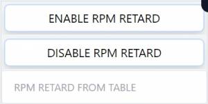
| 11 | RPM RETARD FROM TABLE | RPMRTRD | ReadOnly | INT16 |
| 12 | SERIAL RETARD FROM REMOTE | SERIALRTRDRMT | ReadOnly | INT16 |
| 13 | MAX INDIVIDUAL OFFSET | MAXINDVOFFSET | ReadOnly | INT16 |
| 14 | STANDARD INDIVIDUAL OFFSET | STDINDVOFFSET | ReadOnly | INT16 |
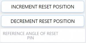
| 15 | REFERENCE ANGLE OF RESET PIN | REFANGLERST | ReadOnly | INT16 |
| 16 | NUMBER OF CYLINDERS | NUMCYLINDERS | ReadOnly | INT16 |
| 17 | ENGINE AVERAGE DIAG | BNKACAVG | ReadOnly | INT16 |
| 18 | ENGINE AVERAGE DIAG BANK B | BNKBCAVG | ReadOnly | INT16 |
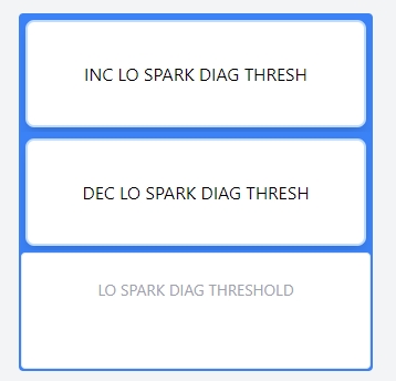
| 19 | LO SPARK DIAG THRESHOLD | LOSPKTHRESH | ReadOnly | INT16 |
| 20 | HI SPARK DIAG THRESHOLD | HISPKTHRESH | ReadOnly | INT16 |
| 21 | NO SPARK DIAG THRESHOLD | NOSPKTHRESH | ReadOnly | INT16 |
| 22 | LO FROM ENGINE THRESHOLD | LOENGTHRESH | ReadOnly | INT16 |
| 23 | HI FROM ENGINE THRESHOLD | HIENGTHRESH | ReadOnly | INT16 |
| 24 | HI VARIATION THRESHOLD | HIVARTHRESH | ReadOnly | INT16 |
| 25 | E2 ENABLE THRESHOLD | E2ENABLETHRESH | ReadOnly | INT16 |
| 26 | E2 DISABLE HYSTERISIS | E2DISABLEHYST | ReadOnly | INT16 |
| 27 | E3 ENABLE THRESHOLD | E3ENABLETHRESH | ReadOnly | INT16 |
| 28 | E3 DISABLE HYSTERISIS | E3DISABLEHYST | ReadOnly | INT16 |
| 29 | LO SPARK BANK B THRESHOLD | LOSPKTHRESHB | ReadOnly | INT16 |
| 30 | HI SPARK BANK B THRESHOLD | HISPKTHRESHB | ReadOnly | INT16 |
| 31 | LO FROM ENG B THRESHOLD | LOENGTHRESHB | ReadOnly | INT16 |
| 32 | HI FROM ENG B THRESHOLD | HIENGTHRESHB | ReadOnly | INT16 |
| 33 | CYL TIMING OFFSET *C1* (A or A1) | CINDVTMG01 | ReadOnly | UINT16 |
| 34 | CYL TIMING OFFSET *C2* (B or A2) | CINDVTMG02 | ReadOnly | UINT16 |
| 35 | CYL TIMING OFFSET *C3* (C or B1) | CINDVTMG03 | ReadOnly | UINT16 |
| 36 | CYL TIMING OFFSET *C4* (D or B2) | CINDVTMG04 | ReadOnly | UINT16 |
| 37 | CYL TIMING OFFSET *C5* (E or C1) | CINDVTMG05 | ReadOnly | UINT16 |
| 38 | CYL TIMING OFFSET *C6* (F or C2) | CINDVTMG06 | ReadOnly | UINT16 |
| 39 | CYL TIMING OFFSET *C7* (G or D1) | CINDVTMG07 | ReadOnly | UINT16 |
| 40 | CYL TIMING OFFSET *C8* (H or D2) | CINDVTMG08 | ReadOnly | UINT16 |
| 41 | CYL TIMING OFFSET *C9* (J or E1) | CINDVTMG09 | ReadOnly | UINT16 |
| 42 | CYL TIMING OFFSET *C10* (K or E2) | CINDVTMG10 | ReadOnly | UINT16 |
| 43 | CYL TIMING OFFSET *C11* (L or F1) | CINDVTMG11 | ReadOnly | UINT16 |
| 44 | CYL TIMING OFFSET *C12* (M or F2) | CINDVTMG12 | ReadOnly | UINT16 |
| 45 | CYL TIMING OFFSET *C13* (R or G1) | CINDVTMG13 | ReadOnly | UINT16 |
| 46 | CYL TIMING OFFSET *C14* (S or G2) | CINDVTMG14 | ReadOnly | UINT16 |
| 47 | CYL TIMING OFFSET *C15* (T or H1) | CINDVTMG15 | ReadOnly | UINT16 |
| 48 | CYL TIMING OFFSET *C16* (Y or H2) | CINDVTMG16 | ReadOnly | UINT16 |
| 49 | CYL TIMING OFFSET *C17* ( J1) | CINDVTMG17 | ReadOnly | UINT16 |
| 50 | CYL TIMING OFFSET *C18* ( J2) | CINDVTMG18 | ReadOnly | UINT16 |
| 51 | CYL TIMING OFFSET *C19* ( K1) | CINDVTMG19 | ReadOnly | UINT16 |
| 52 | CYL TIMING OFFSET *C20* ( K2) | CINDVTMG20 | ReadOnly | UINT16 |
| 53 | CYL TIMING OFFSET *C21* ( L1) | CINDVTMG21 | ReadOnly | UINT16 |
| 54 | CYL TIMING OFFSET *C22* ( L2) | CINDVTMG22 | ReadOnly | UINT16 |
| 55 | CYL TIMING OFFSET *C23* ( M1) | CINDVTMG23 | ReadOnly | UINT16 |
| 56 | CYL TIMING OFFSET *C24* ( M2) | CINDVTMG24 | ReadOnly | UINT16 |
| 57 | CYL TIMING OFFSET *C25* ( R1) | CINDVTMG25 | ReadOnly | UINT16 |
| 58 | CYL TIMING OFFSET *C26* ( R2) | CINDVTMG26 | ReadOnly | UINT16 |
| 59 | CYL TIMING OFFSET *C27* ( S1) | CINDVTMG27 | ReadOnly | UINT16 |
| 60 | CYL TIMING OFFSET *C28* ( S2) | CINDVTMG28 | ReadOnly | UINT16 |
| 61 | CYL TIMING OFFSET *C29* ( T1) | CINDVTMG29 | ReadOnly | UINT16 |
| 62 | CYL TIMING OFFSET *C30* ( T2) | CINDVTMG30 | ReadOnly | UINT16 |
| 63 | CYL TIMING OFFSET *C31* ( U1) | CINDVTMG31 | ReadOnly | UINT16 |
| 64 | CYL TIMING OFFSET *C32* ( U2) | CINDVTMG32 | ReadOnly | UINT16 |
| 65 | DEFAULT OFFSET *C1* (A or A1) | CINDVDEF01 | ReadOnly | UINT16 |
| 66 | DEFAULT OFFSET *C2* (B or A2) | CINDVDEF02 | ReadOnly | UINT16 |
| 67 | DEFAULT OFFSET *C3* (C or B1) | CINDVDEF03 | ReadOnly | UINT16 |
| 68 | DEFAULT OFFSET *C4* (D or B2) | CINDVDEF04 | ReadOnly | UINT16 |
| 69 | DEFAULT OFFSET *C5* (E or C1) | CINDVDEF05 | ReadOnly | UINT16 |
| 70 | DEFAULT OFFSET *C6* (F or C2) | CINDVDEF06 | ReadOnly | UINT16 |
| 71 | DEFAULT OFFSET *C7* (G or D1) | CINDVDEF07 | ReadOnly | UINT16 |
| 72 | DEFAULT OFFSET *C8* (H or D2) | CINDVDEF08 | ReadOnly | UINT16 |
| 73 | DEFAULT OFFSET *C9* (J or E1) | CINDVDEF09 | ReadOnly | UINT16 |
| 74 | DEFAULT OFFSET *C10* (K or E2) | CINDVDEF10 | ReadOnly | UINT16 |
| 75 | DEFAULT OFFSET *C11* (L or F1) | CINDVDEF11 | ReadOnly | UINT16 |
| 76 | DEFAULT OFFSET *C12* (M or F2) | CINDVDEF12 | ReadOnly | UINT16 |
| 77 | DEFAULT OFFSET *C13* (R or G1) | CINDVDEF13 | ReadOnly | UINT16 |
| 78 | DEFAULT OFFSET *C14* (S or G2) | CINDVDEF14 | ReadOnly | UINT16 |
| 79 | DEFAULT OFFSET *C15* (T or H1) | CINDVDEF15 | ReadOnly | UINT16 |
| 80 | DEFAULT OFFSET *C16* ( H2) | CINDVDEF16 | ReadOnly | UINT16 |
| 81 | DEFAULT OFFSET *C17* ( J1) | CINDVDEF17 | ReadOnly | UINT16 |
| 82 | DEFAULT OFFSET *C18* ( J2) | CINDVDEF18 | ReadOnly | UINT16 |
| 83 | DEFAULT OFFSET *C19* ( K1) | CINDVDEF19 | ReadOnly | UINT16 |
| 84 | DEFAULT OFFSET *C20* ( K2) | CINDVDEF20 | ReadOnly | UINT16 |
| 85 | DEFAULT OFFSET *C21* ( L1) | CINDVDEF21 | ReadOnly | UINT16 |
| 86 | DEFAULT OFFSET *C22* ( L2) | CINDVDEF22 | ReadOnly | UINT16 |
| 87 | DEFAULT OFFSET *C23* ( M1) | CINDVDEF23 | ReadOnly | UINT16 |
| 88 | DEFAULT OFFSET *C24* ( M2) | CINDVDEF24 | ReadOnly | UINT16 |
| 89 | DEFAULT OFFSET *C25* ( R1) | CINDVDEF25 | ReadOnly | UINT16 |
| 90 | DEFAULT OFFSET *C26* ( R2) | CINDVDEF26 | ReadOnly | UINT16 |
| 91 | DEFAULT OFFSET *C27* ( S1) | CINDVDEF27 | ReadOnly | UINT16 |
| 92 | DEFAULT OFFSET *C28* ( S2) | CINDVDEF28 | ReadOnly | UINT16 |
| 93 | DEFAULT OFFSET *C29* ( T1) | CINDVDEF29 | ReadOnly | UINT16 |
| 94 | DEFAULT OFFSET *C30* ( T2) | CINDVDEF30 | ReadOnly | UINT16 |
| 95 | DEFAULT OFFSET *C31* ( U1) | CINDVDEF31 | ReadOnly | UINT16 |
| 96 | DEFAULT OFFSET *C32* ( U2) | CINDVDEF32 | ReadOnly | UINT16 |
| 97 | CAVG *C1* (A or A1) | CAVG01 | ReadOnly | INT16 |
| 98 | CAVG *C2* (B or A2) | CAVG02 | ReadOnly | INT16 |
| 99 | CAVG *C3* (C or B1) | CAVG03 | ReadOnly | INT16 |
| 100 | CAVG *C4* (D or B2) | CAVG04 | ReadOnly | INT16 |
| 101 | CAVG *C5* (E or C1) | CAVG05 | ReadOnly | INT16 |
| 102 | CAVG *C6* (F or C2) | CAVG06 | ReadOnly | INT16 |
| 103 | CAVG *C7* (G or D1) | CAVG07 | ReadOnly | INT16 |
| 104 | CAVG *C8* (H or D2) | CAVG08 | ReadOnly | INT16 |
| 105 | CAVG *C9* (J or E1) | CAVG09 | ReadOnly | INT16 |
| 106 | CAVG *C10* (K or E2) | CAVG10 | ReadOnly | INT16 |
| 107 | CAVG *C11* (L or F1) | CAVG11 | ReadOnly | INT16 |
| 108 | CAVG *C12* (M or F2) | CAVG12 | ReadOnly | INT16 |
| 109 | CAVG *C13* (R or G1) | CAVG13 | ReadOnly | INT16 |
| 110 | CAVG *C14* (S or G2) | CAVG14 | ReadOnly | INT16 |
| 111 | CAVG *C15* (T or H1) | CAVG15 | ReadOnly | INT16 |
| 112 | CAVG *C16* (U or H2) | CAVG16 | ReadOnly | INT16 |
| 113 | CAVG *C17* ( J1) | CAVG17 | ReadOnly | INT16 |
| 114 | CAVG *C18* ( J2) | CAVG18 | ReadOnly | INT16 |
| 115 | CAVG *C19* ( K1) | CAVG19 | ReadOnly | INT16 |
| 116 | CAVG *C20* ( K2) | CAVG20 | ReadOnly | INT16 |
| 117 | CAVG *C21* ( L1) | CAVG21 | ReadOnly | INT16 |
| 118 | CAVG *C22* ( L2) | CAVG22 | ReadOnly | INT16 |
| 119 | CAVG *C23* ( M1) | CAVG23 | ReadOnly | INT16 |
| 120 | CAVG *C24* ( M2) | CAVG24 | ReadOnly | INT16 |
| 121 | CAVG *C25* ( R1) | CAVG25 | ReadOnly | INT16 |
| 122 | CAVG *C26* ( R2) | CAVG26 | ReadOnly | INT16 |
| 123 | CAVG *C27* ( S1) | CAVG27 | ReadOnly | INT16 |
| 124 | CAVG *C28* ( S2) | CAVG28 | ReadOnly | INT16 |
| 125 | CAVG *C29* ( T1) | CAVG29 | ReadOnly | INT16 |
| 126 | CAVG *C30* ( T2) | CAVG30 | ReadOnly | INT16 |
| 127 | CAVG *C31* ( U1) | CAVG31 | ReadOnly | INT16 |
| 128 | CAVG *C32* ( U2) | CAVG32 | ReadOnly | INT16 |
| 129 | COV *C1* (A or A1) | COV01 | ReadOnly | INT16 |
| 130 | COV *C2* (B or A2) | COV02 | ReadOnly | INT16 |
| 131 | COV *C3* (C or B1) | COV03 | ReadOnly | INT16 |
| 132 | COV *C4* (D or B2) | COV04 | ReadOnly | INT16 |
| 133 | COV *C5* (E or C1) | COV05 | ReadOnly | INT16 |
| 134 | COV *C6* (F or C2) | COV06 | ReadOnly | INT16 |
| 135 | COV *C7* (G or D1) | COV07 | ReadOnly | INT16 |
| 136 | COV *C8* (H or D2) | COV08 | ReadOnly | INT16 |
| 137 | COV *C9* (J or E1) | COV09 | ReadOnly | INT16 |
| 138 | COV *C10* (K or E2) | COV10 | ReadOnly | INT16 |
| 139 | COV *C11* (L or F1) | COV11 | ReadOnly | INT16 |
| 140 | COV *C12* (M or F2) | COV12 | ReadOnly | INT16 |
| 141 | COV *C13* (R or G1) | COV13 | ReadOnly | INT16 |
| 142 | COV *C14* (S or G2) | COV14 | ReadOnly | INT16 |
| 143 | COV *C15* (T or H1) | COV15 | ReadOnly | INT16 |
| 144 | COV *C16* (U or H2) | COV16 | ReadOnly | INT16 |
| 145 | COV *C17* ( J1) | COV17 | ReadOnly | INT16 |
| 146 | COV *C18* ( J2) | COV18 | ReadOnly | INT16 |
| 147 | COV *C19* ( K1) | COV19 | ReadOnly | INT16 |
| 148 | COV *C20* ( K2) | COV20 | ReadOnly | INT16 |
| 149 | COV *C21* ( L1) | COV21 | ReadOnly | INT16 |
| 150 | COV *C22* ( L2) | COV22 | ReadOnly | INT16 |
| 151 | COV *C23* ( M1) | COV23 | ReadOnly | INT16 |
| 152 | COV *C24* ( M2) | COV24 | ReadOnly | INT16 |
| 153 | COV *C25* ( R1) | COV25 | ReadOnly | INT16 |
| 154 | COV *C26* ( R2) | COV26 | ReadOnly | INT16 |
| 155 | COV *C27* ( S1) | COV27 | ReadOnly | INT16 |
| 156 | COV *C28* ( S2) | COV28 | ReadOnly | INT16 |
| 157 | COV *C29* ( T1) | COV29 | ReadOnly | INT16 |
| 158 | COV *C30* ( T2) | COV30 | ReadOnly | INT16 |
| 159 | COV *C31* ( U1) | COV31 | ReadOnly | INT16 |
| 160 | COV *C32* ( U2) | COV32 | ReadOnly | INT16 |
| 161 | DIAG OFFSET *C1* (A or A1) | DIAGOFST01 | ReadOnly | INT16 |
| 162 | DIAG OFFSET *C2* (B or A2) | DIAGOFST02 | ReadOnly | INT16 |
| 163 | DIAG OFFSET *C3* (C or B1) | DIAGOFST03 | ReadOnly | INT16 |
| 164 | DIAG OFFSET *C4* (D or B2) | DIAGOFST04 | ReadOnly | INT16 |
| 165 | DIAG OFFSET *C5* (E or C1) | DIAGOFST05 | ReadOnly | INT16 |
| 166 | DIAG OFFSET *C6* (F or C2) | DIAGOFST06 | ReadOnly | INT16 |
| 167 | DIAG OFFSET *C7* (G or D1) | DIAGOFST07 | ReadOnly | INT16 |
| 168 | DIAG OFFSET *C8* (H or D2) | DIAGOFST08 | ReadOnly | INT16 |
| 169 | DIAG OFFSET *C9* (J or E1) | DIAGOFST09 | ReadOnly | INT16 |
| 170 | DIAG OFFSET *C10* (K or E2) | DIAGOFST10 | ReadOnly | INT16 |
| 171 | DIAG OFFSET *C11* (L or F1) | DIAGOFST11 | ReadOnly | INT16 |
| 172 | DIAG OFFSET *C12* (M or F2) | DIAGOFST12 | ReadOnly | INT16 |
| 173 | DIAG OFFSET *C13* (R or G1) | DIAGOFST13 | ReadOnly | INT16 |
| 174 | DIAG OFFSET *C14* (S or G2) | DIAGOFST14 | ReadOnly | INT16 |
| 175 | DIAG OFFSET *C15* (T or H1) | DIAGOFST15 | ReadOnly | INT16 |
| 176 | DIAG OFFSET *C16* (U or H2) | DIAGOFST16 | ReadOnly | INT16 |
| 177 | DIAG OFFSET *C17* ( J1) | DIAGOFST17 | ReadOnly | INT16 |
| 178 | DIAG OFFSET *C18* ( J2) | DIAGOFST18 | ReadOnly | INT16 |
| 179 | DIAG OFFSET *C19* ( K1) | DIAGOFST19 | ReadOnly | INT16 |
| 180 | DIAG OFFSET *C20* ( K2) | DIAGOFST20 | ReadOnly | INT16 |
| 181 | DIAG OFFSET *C21* ( L1) | DIAGOFST21 | ReadOnly | INT16 |
| 182 | DIAG OFFSET *C22* ( L2) | DIAGOFST22 | ReadOnly | INT16 |
| 183 | DIAG OFFSET *C23* ( M1) | DIAGOFST23 | ReadOnly | INT16 |
| 184 | DIAG OFFSET *C24* ( M2) | DIAGOFST24 | ReadOnly | INT16 |
| 185 | DIAG OFFSET *C25* ( R1) | DIAGOFST25 | ReadOnly | INT16 |
| 186 | DIAG OFFSET *C26* ( R2) | DIAGOFST26 | ReadOnly | INT16 |
| 187 | DIAG OFFSET *C27* ( S1) | DIAGOFST27 | ReadOnly | INT16 |
| 188 | DIAG OFFSET *C28* ( S2) | DIAGOFST28 | ReadOnly | INT16 |
| 189 | DIAG OFFSET *C29* ( T1) | DIAGOFST29 | ReadOnly | INT16 |
| 190 | DIAG OFFSET *C30* ( T2) | DIAGOFST30 | ReadOnly | INT16 |
| 191 | DIAG OFFSET *C31* ( U1) | DIAGOFST31 | ReadOnly | INT16 |
| 192 | DIAG OFFSET *C32* ( U2) | DIAGOFST32 | ReadOnly | INT16 |
| 193 | spare193 | spare300193 | ReadOnly | UINT16 |
| 194 | spare194 | spare300194 | ReadOnly | UINT16 |
| 195 | spare195 | spare300195 | ReadOnly | UINT16 |
| 196 | spare196 | spare300196 | ReadOnly | UINT16 |
| 197 | spare197 | spare300197 | ReadOnly | UINT16 |
| 198 | spare198 | spare300198 | ReadOnly | UINT16 |
| 199 | spare199 | spare300199 | ReadOnly | UINT16 |
| 200 | spare200 | spare300200 | ReadOnly | UINT16 |
| 201 | spare201 | spare300201 | ReadOnly | UINT16 |
| 202 | spare202 | spare300202 | ReadOnly | UINT16 |
| 203 | spare203 | spare300203 | ReadOnly | UINT16 |
| 204 | spare204 | spare300204 | ReadOnly | UINT16 |
| 205 | spare205 | spare300205 | ReadOnly | UINT16 |
| 206 | spare206 | spare300206 | ReadOnly | UINT16 |
| 207 | spare207 | spare300207 | ReadOnly | UINT16 |
| 208 | spare208 | spare300208 | ReadOnly | UINT16 |
| 209 | spare209 | spare300209 | ReadOnly | UINT16 |
| 210 | firmware date | TUINT32 | ReadOnly | UINT32 |
| 212 | TEST INT32 | TINT32 | ReadOnly | INT32 |
| 214 | firmware progress | TFLT32 | ReadOnly | FLOAT32 |
| 220 | TEST 220 | T220 | ReadOnly | UINT16 |
| 227 | TEST 227 | T227 | ReadOnly | UINT16 |
| 230 | TEST 230 | T230 | ReadOnly | UINT16 |
| 253 | CYCLE AND COM CONFIG DATA | CONFIGCYCCOM | ReadOnly | INT16 |
| 254 | ID CODE FOR LOGIC SER PORT | IDCODEMB | ReadOnly | INT16 |
| 255 | KEYCMD REQUEST REGISTER | KEYCMD | ReadOnly | INT16 |
| 256 | KEYCMD DATA REGISTER | KEYCMDDAT | ReadOnly | INT16 |
| 371 | ENGINE STATE | ENGSTATE | ReadOnly | INT16 |
| 372 | SYNCING FLAG | FLGSYNCING | ReadOnly | UINT16 |
| 373 | INSYNC FLAG | FLGINSYNC | ReadOnly | UINT16 |
| 374 | FIRING FLAG | FLGFIRING | ReadOnly | UINT16 |
| 375 | STALLED FLAG | FLGSTALLED | ReadOnly | UINT16 |
| 376 | FAULT FLAG | FLGFAULT | ReadOnly | UINT16 |
| 377 | SHUTDOWN INPUT | FLGSHTDWN | ReadOnly | UINT16 |
| 378 | ROTATING FLAG | FLGROTATING | ReadOnly | UINT16 |
| 379 | OVERSPEED FLAG | FLGOVERSPD | ReadOnly | UINT16 |
| 380 | GEAR TOOTH SEEN | FLGGTSEEN | ReadOnly | UINT16 |
| 381 | RST SEEN | FLGRSTSEEN | ReadOnly | UINT16 |
| 382 | CAM SEEN | FLGCAMSEEN | ReadOnly | UINT16 |
| 383 | GEARTEETH PER RESET | GTPERRST | ReadOnly | UINT16 |
| 384 | GEARTEETH SINCE RESET | GTSINCERST | ReadOnly | UINT16 |
| 385 | GEARTEETH PER CAM | GTPERCAM | ReadOnly | UINT16 |
| 386 | GEARTEETH SINCE CAM | GTSINCECAM | ReadOnly | UINT16 |
| 387 | LAST CONDITION | LSTCOND | ReadOnly | UINT16 |
| 388 | ENERGY LEVEL | ENRGLVL | ReadOnly | UINT16 |
| 401 | 1R P Secondary Voltage | CYL1kv | ReadOnly | UINT16 |
| 402 | 4R P Secondary Voltage | CYL2kv | ReadOnly | UINT16 |
| 403 | 3R P Secondary Voltage | CYL3kv | ReadOnly | UINT16 |
| 404 | 2R P Secondary Voltage | CYL4kv | ReadOnly | UINT16 |
| 405 | 5R P Secondary Voltage | CYL5kv | ReadOnly | UINT16 |
| 406 | 1R O Secondary Voltage | CYL6kv | ReadOnly | UINT16 |
| 407 | 4R O Secondary Voltage | CYL7kv | ReadOnly | UINT16 |
| 408 | 3R O Secondary Voltage | CYL8kv | ReadOnly | UINT16 |
| 409 | 2R O Secondary Voltage | CYL9kv | ReadOnly | UINT16 |
| 410 | 5R O Secondary Voltage | CYL10kv | ReadOnly | UINT16 |
| 411 | 1L P Secondary Voltage | CYL11kv | ReadOnly | UINT16 |
| 412 | 4L P Secondary Voltage | CYL12kv | ReadOnly | UINT16 |
| 413 | 3L P Secondary Voltage | CYL13kv | ReadOnly | UINT16 |
| 414 | 2L P Secondary Voltage | CYL14kv | ReadOnly | UINT16 |
| 415 | 5L P Secondary Voltage | CYL15kv | ReadOnly | UINT16 |
| 416 | 1L O Secondary Voltage | CYL16kv | ReadOnly | UINT16 |
| 417 | 4L O Secondary Voltage | CYL17kv | ReadOnly | UINT16 |
| 418 | 3L O Secondary Voltage | CYL18kv | ReadOnly | UINT16 |
| 419 | 2L O Secondary Voltage | CYL19kv | ReadOnly | UINT16 |
| 420 | 5L O Secondary Voltage | CYL20kv | ReadOnly | UINT16 |
| 421 | CYL 21 Secondary Voltage | CYL21kv | ReadOnly | UINT16 |
| 422 | CYL 22 Secondary Voltage | CYL22kv | ReadOnly | UINT16 |
| 423 | CYL 23 Secondary Voltage | CYL23kv | ReadOnly | UINT16 |
| 424 | CYL 24 Secondary Voltage | CYL24kv | ReadOnly | UINT16 |
| 425 | CYL 25 Secondary Voltage | CYL25kv | ReadOnly | UINT16 |
| 426 | CYL 26 Secondary Voltage | CYL26kv | ReadOnly | UINT16 |
| 427 | CYL 27 Secondary Voltage | CYL27kv | ReadOnly | UINT16 |
| 428 | CYL 28 Secondary Voltage | CYL28kv | ReadOnly | UINT16 |
| 429 | CYL 29 Secondary Voltage | CYL29kv | ReadOnly | UINT16 |
| 430 | CYL 30 Secondary Voltage | CYL30kv | ReadOnly | UINT16 |
| 431 | CYL 31 Secondary Voltage | CYL31kv | ReadOnly | UINT16 |
| 432 | CYL 32 Secondary Voltage | CYL32kv | ReadOnly | UINT16 |
| 433 | CYL 33 Secondary Voltage | CYL33kv | ReadOnly | UINT16 |
| 434 | CYL 34 Secondary Voltage | CYL34kv | ReadOnly | UINT16 |
| 435 | CYL 35 Secondary Voltage | CYL35kv | ReadOnly | UINT16 |
| 436 | CYL 36 Secondary Voltage | CYL36kv | ReadOnly | UINT16 |
| 437 | CYL 37 Secondary Voltage | CYL37kv | ReadOnly | UINT16 |
| 438 | CYL 38 Secondary Voltage | CYL38kv | ReadOnly | UINT16 |
| 439 | CYL 39 Secondary Voltage | CYL39kv | ReadOnly | UINT16 |
| 440 | CYL 40 Secondary Voltage | CYL40kv | ReadOnly | UINT16 |
| 500 | Engine Config Num Cylinders | eNumCyl | INT16 | |
| 501 | Engine Config Type | eType | INT16 | |
| 502 | Engine Config Coils Per Cylinder | eCoilPerCyl | INT16 | |
| 503 | Engine Config Max RPM | eMaxRpm | INT16 | |
| 504 | Engine Config FP 2 Cylinder Flag | eFp2cyl | INT16 | |
| 505 | Engine Config FP 2nd Cylinder Offset | eFp2ndCylOfst | INT16 | |
| 506 | Engine Config Num Gear Teeth | eGearTeeth | INT16 | |
| 507 | Engine Config Output Module | eOutputMod | INT16 | |
| 508 | Engine Config Coils Per Output | eCoilPerOutp | INT16 | |
| 509 | FireA Angle0 | eFireA0 | INT16 | |
| 510 | FireA Angle1 | eFireA1 | INT16 | |
| 511 | FireA Angle2 | eFireA2 | INT16 | |
| 512 | FireA Angle3 | eFireA3 | INT16 | |
| 513 | FireA Angle4 | eFireA4 | INT16 | |
| 514 | FireA Angle5 | eFireA5 | INT16 | |
| 515 | FireA Angle6 | eFireA6 | INT16 | |
| 516 | FireA Angle7 | eFireA7 | INT16 | |
| 517 | FireA Angle8 | eFireA8 | INT16 | |
| 518 | FireA Angle9 | eFireA9 | INT16 | |
| 519 | FireA Angle10 | eFireA10 | INT16 | |
| 520 | FireA Angle11 | eFireA11 | INT16 | |
| 521 | FireA Angle12 | eFireA12 | INT16 | |
| 522 | FireA Angle13 | eFireA13 | INT16 | |
| 523 | FireA Angle14 | eFireA14 | INT16 | |
| 524 | FireA Angle15 | eFireA15 | INT16 | |
| 525 | FireA Angle16 | eFireA16 | INT16 | |
| 526 | FireA Angle17 | eFireA17 | INT16 | |
| 527 | FireA Angle18 | eFireA18 | INT16 | |
| 528 | FireA Angle19 | eFireA19 | INT16 | |
| 529 | FireB Angle0 | eFireB0 | INT16 | |
| 530 | FireB Angle1 | eFireB1 | INT16 | |
| 531 | FireB Angle2 | eFireB2 | INT16 | |
| 532 | FireB Angle3 | eFireB3 | INT16 | |
| 533 | FireB Angle4 | eFireB4 | INT16 | |
| 534 | FireB Angle5 | eFireB5 | INT16 | |
| 535 | FireB Angle6 | eFireB6 | INT16 | |
| 536 | FireB Angle7 | eFireB7 | INT16 | |
| 537 | FireB Angle8 | eFireB8 | INT16 | |
| 538 | FireB Angle9 | eFireB9 | INT16 | |
| 539 | FireB Angle10 | eFireB10 | INT16 | |
| 540 | FireB Angle11 | eFireB11 | INT16 | |
| 541 | FireB Angle12 | eFireB12 | INT16 | |
| 542 | FireB Angle13 | eFireB13 | INT16 | |
| 543 | FireB Angle14 | eFireB14 | INT16 | |
| 544 | FireB Angle15 | eFireB15 | INT16 | |
| 545 | FireB Angle16 | eFireB16 | INT16 | |
| 546 | FireB Angle17 | eFireB17 | INT16 | |
| 547 | FireB Angle18 | eFireB18 | INT16 | |
| 548 | FireB Angle19 | eFireB19 | INT16 | |
| 549 | Current Map Current0 | eCurMap0c | INT16 | |
| 550 | Current Map Retard0 | eCurMap0r | INT16 | |
| 551 | Current Map Current1 | eCurMap1c | INT16 | |
| 552 | Current Map Retard1 | eCurMap1r | INT16 | |
| 553 | Current Map Current2 | eCurMap2c | INT16 | |
| 554 | Current Map Retard2 | eCurMap2r | INT16 | |
| 555 | Current Map Current3 | eCurMap3c | INT16 | |
| 556 | Current Map Retard3 | eCurMap3r | INT16 | |
| 557 | Current Map Current4 | eCurMap4c | INT16 | |
| 558 | Current Map Retard4 | eCurMap4r | INT16 | |
| 559 | Current Map Current5 | eCurMap5c | INT16 | |
| 560 | Current Map Retard5 | eCurMap5r | INT16 | |
| 561 | Current Map Current6 | eCurMap6c | INT16 | |
| 562 | Current Map Retard6 | eCurMap6r | INT16 | |
| 563 | Current Map Current7 | eCurMap7c | INT16 | |
| 564 | Current Map Retard7 | eCurMap7r | INT16 | |
| 565 | Current Map Current8 | eCurMap8c | INT16 | |
| 566 | Current Map Retard8 | eCurMap8r | INT16 | |
| 567 | Current Map Current9 | eCurMap9c | INT16 | |
| 568 | Current Map Retard9 | eCurMap9r | INT16 | |
| 569 | Current Map Current10 | eCurMap10c | INT16 | |
| 570 | Current Map Retard10 | eCurMap10r | INT16 | |
| 571 | Current Map Current11 | eCurMap11c | INT16 | |
| 572 | Current Map Retard11 | eCurMap11r | INT16 | |
| 573 | Current Map Current12 | eCurMap12c | INT16 | |
| 574 | Current Map Retard12 | eCurMap12r | INT16 | |
| 575 | Current Map Current13 | eCurMap13c | INT16 | |
| 576 | Current Map Retard13 | eCurMap13r | INT16 | |
| 577 | Current Map Current14 | eCurMap14c | INT16 | |
| 578 | Current Map Retard14 | eCurMap14r | INT16 | |
| 579 | RPM Map Speed0 | eRpmMap0s | INT16 | |
| 580 | RPM Map Retard0 | eRpmMap0r | INT16 | |
| 581 | RPM Map Speed1 | eRpmMap1s | INT16 | |
| 582 | RPM Map Retard1 | eRpmMap1r | INT16 | |
| 583 | RPM Map Speed2 | eRpmMap2s | INT16 | |
| 584 | RPM Map Retard2 | eRpmMap2r | INT16 | |
| 585 | RPM Map Speed3 | eRpmMap3s | INT16 | |
| 586 | RPM Map Retard3 | eRpmMap3r | INT16 | |
| 587 | RPM Map Speed4 | eRpmMap4s | INT16 | |
| 588 | RPM Map Retard4 | eRpmMap4r | INT16 | |
| 589 | RPM Map Speed5 | eRpmMap5s | INT16 | |
| 590 | RPM Map Retard5 | eRpmMap5r | INT16 | |
| 591 | RPM Map Speed6 | eRpmMap6s | INT16 | |
| 592 | RPM Map Retard6 | eRpmMap6r | INT16 | |
| 593 | RPM Map Speed7 | eRpmMap7s | INT16 | |
| 594 | RPM Map Retard7 | eRpmMap7r | INT16 | |
| 595 | RPM Map Speed8 | eRpmMap8s | INT16 | |
| 596 | RPM Map Retard8 | eRpmMap8r | INT16 | |
| 597 | RPM Map Speed9 | eRpmMap9s | INT16 | |
| 598 | RPM Map Retard9 | eRpmMap9r | INT16 | |
| 599 | RPM Map Speed10 | eRpmMap10s | INT16 | |
| 600 | RPM Map Retard10 | eRpmMap10r | INT16 | |
| 601 | RPM Map Speed11 | eRpmMap11s | INT16 | |
| 602 | RPM Map Retard11 | eRpmMap11r | INT16 | |
| 603 | RPM Map Speed12 | eRpmMap12s | INT16 | |
| 604 | RPM Map Retard12 | eRpmMap12r | INT16 | |
| 605 | RPM Map Speed13 | eRpmMap13s | INT16 | |
| 606 | RPM Map Retard13 | eRpmMap13r | INT16 | |
| 607 | RPM Map Speed14 | eRpmMap14s | INT16 | |
| 608 | RPM Map Retard14 | eRpmMap14r | INT16 | |
| 609 | Engine Config Advanced Timing Value | eAtv | INT16 | |
| 610 | Engine Config Advanced Energy Value | eAev | INT16 | |
| 611 | Engine Config Advanced Fire Value | eAfv | INT16 | |
| 612 | Engine Config Test Mode Permit | eTmPermit | ReadOnly | INT16 |
| 613 | Fire Pattern Enum | eFireEnum | INT16 | |
| 614 | Engine Config System Type | eOutMod | INT16 | |
| 615 | Engine Config Chksum | eChksum | INT16 | |
| 616 | Engine Config Go | eGo | INT16 | |
| 1000 | Bootloader State | BOOTSTATE | UINT16 | |
| 1001 | RESERVED500 | DIAGALRM01 | ReadOnly | UINT16 |
| 1002 | RESERVED501 | DIAGALRM02 | ReadOnly | UINT16 |
| 1003 | RESERVED502 | DIAGALRM03 | ReadOnly | UINT16 |
| 1004 | RESERVED503 | DIAGALRM04 | ReadOnly | UINT16 |
| 1005 | RESERVED504 | DIAGALRM05 | ReadOnly | UINT16 |
| 1006 | RESERVED505 | DIAGALRM06 | ReadOnly | UINT16 |
| 1007 | RESERVED506 | DIAGALRM07 | ReadOnly | UINT16 |
| 1008 | RESERVED507 | DIAGALRM08 | ReadOnly | UINT16 |
| 1009 | RESERVED508 | DIAGALRM09 | ReadOnly | UINT16 |
| 1010 | RESERVED509 | DIAGALRM10 | ReadOnly | UINT16 |
| 1011 | RESERVED510 | DIAGALRM11 | ReadOnly | UINT16 |
| 1012 | RESERVED511 | DIAGALRM12 | ReadOnly | UINT16 |
| 1013 | RESERVED512 | DIAGALRM13 | ReadOnly | UINT16 |
| 1014 | RESERVED513 | DIAGALRM14 | ReadOnly | UINT16 |
| 1015 | RESERVED514 | DIAGALRM15 | ReadOnly | UINT16 |
| 1016 | RESERVED515 | DIAGALRM16 | ReadOnly | UINT16 |
| 1017 | RESERVED516 | DIAGALRM17 | ReadOnly | UINT16 |
| 1018 | RESERVED517 | DIAGALRM18 | ReadOnly | UINT16 |
| 1019 | RESERVED518 | DIAGALRM19 | ReadOnly | UINT16 |
| 1020 | RESERVED519 | DIAGALRM20 | ReadOnly | UINT16 |
| 1021 | RESERVED520 | DIAGALRM21 | ReadOnly | UINT16 |
| 1022 | RESERVED521 | DIAGALRM22 | ReadOnly | UINT16 |
| 1023 | RESERVED522 | DIAGALRM23 | ReadOnly | UINT16 |
| 1024 | RESERVED523 | DIAGALRM24 | ReadOnly | UINT16 |
| 1025 | RESERVED524 | DIAGALRM25 | ReadOnly | UINT16 |
| 1026 | RESERVED525 | DIAGALRM26 | ReadOnly | UINT16 |
| 1027 | RESERVED526 | DIAGALRM27 | ReadOnly | UINT16 |
| 1028 | RESERVED527 | DIAGALRM28 | ReadOnly | UINT16 |
| 1029 | RESERVED528 | DIAGALRM29 | ReadOnly | UINT16 |
| 1030 | RESERVED529 | DIAGALRM30 | ReadOnly | UINT16 |
| 1031 | RESERVED530 | DIAGALRM31 | ReadOnly | UINT16 |
| 1032 | RESERVED531 | DIAGALRM32 | ReadOnly | UINT16 |
| 1033 | DIAG MAX *C1* (A or A1) | DIAGMAX01 | ReadOnly | UINT16 |
| 1034 | DIAG MAX *C2* (B or A2) | DIAGMAX02 | ReadOnly | UINT16 |
| 1035 | DIAG MAX *C3* (C or B1) | DIAGMAX03 | ReadOnly | UINT16 |
| 1036 | DIAG MAX *C4* (D or B2) | DIAGMAX04 | ReadOnly | UINT16 |
| 1037 | DIAG MAX *C5* (E or C1) | DIAGMAX05 | ReadOnly | UINT16 |
| 1038 | DIAG MAX *C6* (F or C2) | DIAGMAX06 | ReadOnly | UINT16 |
| 1039 | DIAG MAX *C7* (G or D1) | DIAGMAX07 | ReadOnly | UINT16 |
| 1040 | DIAG MAX *C8* (H or D2) | DIAGMAX08 | ReadOnly | UINT16 |
| 1041 | DIAG MAX *C9* (J or E1) | DIAGMAX09 | ReadOnly | UINT16 |
| 1042 | DIAG MAX *C10* (K or E2) | DIAGMAX10 | ReadOnly | UINT16 |
| 1043 | DIAG MAX *C11* (L or F1) | DIAGMAX11 | ReadOnly | UINT16 |
| 1044 | DIAG MAX *C12* (M or F2) | DIAGMAX12 | ReadOnly | UINT16 |
| 1045 | DIAG MAX *C13* (R or G1) | DIAGMAX13 | ReadOnly | UINT16 |
| 1046 | DIAG MAX *C14* (S or G2) | DIAGMAX14 | ReadOnly | UINT16 |
| 1047 | DIAG MAX *C15* (T or H1) | DIAGMAX15 | ReadOnly | UINT16 |
| 1048 | DIAG MAX *C16* (Y or H2) | DIAGMAX16 | ReadOnly | UINT16 |
| 1049 | DIAG MAX *C17* ( J1) | DIAGMAX17 | ReadOnly | UINT16 |
| 1050 | DIAG MAX *C18* ( J2) | DIAGMAX18 | ReadOnly | UINT16 |
| 1051 | DIAG MAX *C19* ( K1) | DIAGMAX19 | ReadOnly | UINT16 |
| 1052 | DIAG MAX *C20* ( K2) | DIAGMAX20 | ReadOnly | UINT16 |
| 1053 | DIAG MAX *C21* ( L1) | DIAGMAX21 | ReadOnly | UINT16 |
| 1054 | DIAG MAX *C22* ( L2) | DIAGMAX22 | ReadOnly | UINT16 |
| 1055 | DIAG MAX *C23* ( M1) | DIAGMAX23 | ReadOnly | UINT16 |
| 1056 | DIAG MAX *C24* ( M2) | DIAGMAX24 | ReadOnly | UINT16 |
| 1057 | DIAG MAX *C25* ( R1) | DIAGMAX25 | ReadOnly | UINT16 |
| 1058 | DIAG MAX *C26* ( R2) | DIAGMAX26 | ReadOnly | UINT16 |
| 1059 | DIAG MAX *C27* ( S1) | DIAGMAX27 | ReadOnly | UINT16 |
| 1060 | DIAG MAX *C28* ( S2) | DIAGMAX28 | ReadOnly | UINT16 |
| 1061 | DIAG MAX *C29* ( T1) | DIAGMAX29 | ReadOnly | UINT16 |
| 1062 | DIAG MAX *C30* ( T2) | DIAGMAX30 | ReadOnly | UINT16 |
| 1063 | DIAG MAX *C31* ( U1) | DIAGMAX31 | ReadOnly | UINT16 |
| 1064 | DIAG MAX *C32* ( U2) | DIAGMAX32 | ReadOnly | UINT16 |
| 1065 | DIAG MIN *C1* (A or A1) | DIAGMIN01 | ReadOnly | UINT16 |
| 1066 | DIAG MIN *C2* (B or A2) | DIAGMIN02 | ReadOnly | UINT16 |
| 1067 | DIAG MIN *C3* (C or B1) | DIAGMIN03 | ReadOnly | UINT16 |
| 1068 | DIAG MIN *C4* (D or B2) | DIAGMIN04 | ReadOnly | UINT16 |
| 1069 | DIAG MIN *C5* (E or C1) | DIAGMIN05 | ReadOnly | UINT16 |
| 1070 | DIAG MIN *C6* (F or C2) | DIAGMIN06 | ReadOnly | UINT16 |
| 1071 | DIAG MIN *C7* (G or D1) | DIAGMIN07 | ReadOnly | UINT16 |
| 1072 | DIAG MIN *C8* (H or D2) | DIAGMIN08 | ReadOnly | UINT16 |
| 1073 | DIAG MIN *C9* (J or E1) | DIAGMIN09 | ReadOnly | UINT16 |
| 1074 | DIAGMIN *C10* (K or E2) | DIAGMIN10 | ReadOnly | UINT16 |
| 1075 | DIAGMIN *C11* (L or F1) | DIAGMIN11 | ReadOnly | UINT16 |
| 1076 | DIAG MIN *C12* (M or F2) | DIAGMIN12 | ReadOnly | UINT16 |
| 1077 | DIAG MIN *C13* (R or G1) | DIAGMIN13 | ReadOnly | UINT16 |
| 1078 | DIAG MIN *C14* (S or G2) | DIAGMIN14 | ReadOnly | UINT16 |
| 1079 | DIAG MIN *C15* (T or H1) | DIAGMIN15 | ReadOnly | UINT16 |
| 1080 | DIAG MIN *C16* (Y or H2) | DIAGMIN16 | ReadOnly | UINT16 |
| 1081 | DIAG MIN *C17* ( J1) | DIAGMIN17 | ReadOnly | UINT16 |
| 1082 | DIAG MIN *C18* ( J2) | DIAGMIN18 | ReadOnly | UINT16 |
| 1083 | DIAG MIN *C19* ( K1) | DIAGMIN19 | ReadOnly | UINT16 |
| 1084 | DIAG MIN *C20* ( K2) | DIAGMIN20 | ReadOnly | UINT16 |
| 1085 | DIAG MIN *C21* ( L1) | DIAGMIN21 | ReadOnly | UINT16 |
| 1086 | DIAG MIN *C22* ( L2) | DIAGMIN22 | ReadOnly | UINT16 |
| 1087 | DIAG MIN *C23* ( M1) | DIAGMIN23 | ReadOnly | UINT16 |
| 1088 | DIAG MIN *C24* ( M2) | DIAGMIN24 | ReadOnly | UINT16 |
| 1089 | DIAG MIN *C25* ( R1) | DIAGMIN25 | ReadOnly | UINT16 |
| 1090 | DIAG MIN *C26* ( R2) | DIAGMIN26 | ReadOnly | UINT16 |
| 1091 | DIAG MIN *C27* ( S1) | DIAGMIN27 | ReadOnly | UINT16 |
| 1092 | DIAG MIN *C28* ( S2) | DIAGMIN28 | ReadOnly | UINT16 |
| 1093 | DIAG MIN *C29* ( T1) | DIAGMIN29 | ReadOnly | UINT16 |
| 1094 | DIAG MIN *C30* ( T2) | DIAGMIN30 | ReadOnly | UINT16 |
| 1095 | DIAG MIN *C31* ( U1) | DIAGMIN31 | ReadOnly | UINT16 |
| 1096 | DIAG MIN *C32* ( U2) | DIAGMIN32 | ReadOnly | UINT16 |
| 1097 | DIAG REAL *C1* (A or A1) | DIAGREAL01 | ReadOnly | UINT16 |
| 1098 | DIAGREAL *C2* (B or A2) | DIAGREAL02 | ReadOnly | UINT16 |
| 1099 | DIAG REAL *C3* (C or B1) | DIAGREAL03 | ReadOnly | UINT16 |
| 1100 | DIAG REAL *C4* (D or B2) | DIAGREAL04 | ReadOnly | UINT16 |
| 1101 | DIAG REAL *C5* (E or C1) | DIAGREAL05 | ReadOnly | UINT16 |
| 1102 | DIAG REAL *C6* (F or C2) | DIAGREAL06 | ReadOnly | UINT16 |
| 1103 | DIAG REAL *C7* (G or D1) | DIAGREAL07 | ReadOnly | UINT16 |
| 1104 | DIAG REAL *C8* (H or D2) | DIAGREAL08 | ReadOnly | UINT16 |
| 1105 | DIAG REAL *C9* (J or E1) | DIAGREAL09 | ReadOnly | UINT16 |
| 1106 | DIAG REAL *C10* (K or E2) | DIAGREAL10 | ReadOnly | UINT16 |
| 1107 | DIAG REAL *C11* (L or F1) | DIAGREAL11 | ReadOnly | UINT16 |
| 1108 | DIAG REAL *C12* (M or F2) | DIAGREAL12 | ReadOnly | UINT16 |
| 1109 | DIAG REAL *C13* (R or G1) | DIAGREAL13 | ReadOnly | UINT16 |
| 1110 | DIAG REAL *C14* (S or G2) | DIAGREAL14 | ReadOnly | UINT16 |
| 1111 | DIAG REAL *C15* (T or H1) | DIAGREAL15 | ReadOnly | UINT16 |
| 1112 | DIAG REAL *C16* (Y or H2) | DIAGREAL16 | ReadOnly | UINT16 |
| 1113 | DIAG REAL *C17* ( J1) | DIAGREAL17 | ReadOnly | UINT16 |
| 1114 | DIAG REAL *C18* ( J2) | DIAGREAL18 | ReadOnly | UINT16 |
| 1115 | DIAG REAL *C19* ( K1) | DIAGREAL19 | ReadOnly | UINT16 |
| 1116 | DIAG REAL *C20* ( K2) | DIAGREAL20 | ReadOnly | UINT16 |
| 1117 | DIAG REAL *C21* ( L1) | DIAGREAL21 | ReadOnly | UINT16 |
| 1118 | DIAG REAL *C22* ( L2) | DIAGREAL22 | ReadOnly | UINT16 |
| 1119 | DIAG REAL(*C23*( M1) | DIAGREAL23 | ReadOnly | UINT16 |
| 1120 | DIAG REAL *C24* ( M2) | DIAGREAL24 | ReadOnly | UINT16 |
| 1121 | DIAG REAL *C25* ( R1) | DIAGREAL25 | ReadOnly | UINT16 |
| 1122 | DIAG REAL *C26* ( R2) | DIAGREAL26 | ReadOnly | UINT16 |
| 1123 | DIAG REAL *C27* ( S1) | DIAGREAL27 | ReadOnly | UINT16 |
| 1124 | DIAG REAL *C28* ( S2) | DIAGREAL28 | ReadOnly | UINT16 |
| 1125 | DIAG REAL *C29* ( T1) | DIAGREAL29 | ReadOnly | UINT16 |
| 1126 | DIAG REAL *C30* ( T2) | DIAGREAL30 | ReadOnly | UINT16 |
| 1127 | DIAG REAL *C31* ( U1) | DIAGREAL31 | ReadOnly | UINT16 |
| 1128 | DIAG REAL *C32* ( U2) | DIAGREAL32 | ReadOnly | UINT16 |
| 1129 | DIAG FILT B | DIAGFILTB | ReadOnly | UINT16 |
40000 modbus registers
| Register | Label | Key | ReadOnly / ReadWrite | Type |
| 33 | CYL TIMING OFFSET *C1* (A or A1) | CINDVTMGWR01 | ReadWrite | INT16 |
| 34 | CYL TIMING OFFSET *C2* (B or A2) | CINDVTMGWR02 | ReadWrite | INT16 |
| 35 | CYL TIMING OFFSET *C3* (C or B1) | CINDVTMGWR03 | ReadWrite | INT16 |
| 36 | CYL TIMING OFFSET *C4* (D or B2) | CINDVTMGWR04 | ReadWrite | INT16 |
| 37 | CYL TIMING OFFSET *C5* (E or C1) | CINDVTMGWR05 | ReadWrite | INT16 |
| 38 | CYL TIMING OFFSET *C6* (F or C2) | CINDVTMGWR06 | ReadWrite | INT16 |
| 39 | CYL TIMING OFFSET *C7* (G or D1) | CINDVTMGWR07 | ReadWrite | INT16 |
| 40 | CYL TIMING OFFSET *C8* (H or D2) | CINDVTMGWR08 | ReadWrite | INT16 |
| 41 | CYL TIMING OFFSET *C9* (J or E1) | CINDVTMGWR09 | ReadWrite | INT16 |
| 42 | CYL TIMING OFFSET *C10* (K or E2) | CINDVTMGWR10 | ReadWrite | INT16 |
| 43 | CYL TIMING OFFSET *C11* (L or F1) | CINDVTMGWR11 | ReadWrite | INT16 |
| 44 | CYL TIMING OFFSET *C12* (M or F2) | CINDVTMGWR12 | ReadWrite | INT16 |
| 45 | CYL TIMING OFFSET *C13* (R or G1) | CINDVTMGWR13 | ReadWrite | INT16 |
| 46 | CYL TIMING OFFSET *C14* (S or G2) | CINDVTMGWR14 | ReadWrite | INT16 |
| 47 | CYL TIMING OFFSET *C15* (T or H1) | CINDVTMGWR15 | ReadWrite | INT16 |
| 48 | CYL TIMING OFFSET *C16* (U or H2) | CINDVTMGWR16 | ReadWrite | INT16 |
| 49 | CYL TIMING OFFSET *C17* ( J1) | CINDVTMGWR17 | ReadWrite | INT16 |
| 50 | CYL TIMING OFFSET *C18* ( J2) | CINDVTMGWR18 | ReadWrite | INT16 |
| 51 | CYL TIMING OFFSET *C19* ( K1) | CINDVTMGWR19 | ReadWrite | INT16 |
| 52 | CYL TIMING OFFSET *C20* ( K2) | CINDVTMGWR20 | ReadWrite | INT16 |
| 53 | CYL TIMING OFFSET *C21* ( L1) | CINDVTMGWR21 | ReadWrite | INT16 |
| 54 | CYL TIMING OFFSET *C22* ( L2) | CINDVTMGWR22 | ReadWrite | INT16 |
| 55 | CYL TIMING OFFSET *C23* ( M1) | CINDVTMGWR23 | ReadWrite | INT16 |
| 56 | CYL TIMING OFFSET *C24* ( M2) | CINDVTMGWR24 | ReadWrite | INT16 |
| 57 | CYL TIMING OFFSET *C25* ( R1) | CINDVTMGWR25 | ReadWrite | INT16 |
| 58 | CYL TIMING OFFSET *C26* ( R2) | CINDVTMGWR26 | ReadWrite | INT16 |
| 59 | CYL TIMING OFFSET *C27* ( S1) | CINDVTMGWR27 | ReadWrite | INT16 |
| 60 | CYL TIMING OFFSET *C28* ( S2) | CINDVTMGWR28 | ReadWrite | INT16 |
| 61 | CYL TIMING OFFSET *C29* ( T1) | CINDVTMGWR29 | ReadWrite | INT16 |
| 62 | CYL TIMING OFFSET *C30* ( T2) | CINDVTMGWR30 | ReadWrite | INT16 |
| 63 | CYL TIMING OFFSET *C31* ( U1) | CINDVTMGWR31 | ReadWrite | INT16 |
| 64 | CYL TIMING OFFSET *C32* ( U2) | CINDVTMGWR32 | ReadWrite | INT16 |
| 255 | KEY COMMAND | KEYPRS | ReadWrite | UINT32 |
| 257 | Engine Config Num Cylinders | cNumCyl | INT16 | |
| 258 | Engine Config Type | cType | INT16 | |
| 259 | Engine Config Coils Per Cylinder | cCoilPerCyl | INT16 | |
| 260 | Engine Config Max RPM | cMaxRpm | INT16 | |
| 261 | Engine Config FP 2 Cylinder Flag | cFp2cyl | INT16 | |
| 262 | Engine Config FP 2nd Cylinder Offset | cFp2ndCylOfst | INT16 | |
| 263 | Engine Config Num Gear Teeth | cGearTeeth | INT16 | |
| 264 | Engine Config Output Module | cOutputMod | INT16 | |
| 265 | Engine Config Coils Per Output | cCoilPerOutp | INT16 | |
| 266 | FireA Angle0 | cFireA0 | INT16 | |
| 267 | FireA Angle1 | cFireA1 | INT16 | |
| 268 | FireA Angle2 | cFireA2 | INT16 | |
| 269 | FireA Angle3 | cFireA3 | INT16 | |
| 270 | FireA Angle4 | cFireA4 | INT16 | |
| 271 | FireA Angle5 | cFireA5 | INT16 | |
| 272 | FireA Angle6 | cFireA6 | INT16 | |
| 273 | FireA Angle7 | cFireA7 | INT16 | |
| 274 | FireA Angle8 | cFireA8 | INT16 | |
| 275 | FireA Angle9 | cFireA9 | INT16 | |
| 276 | FireA Angle10 | cFireA10 | INT16 | |
| 277 | FireA Angle11 | cFireA11 | INT16 | |
| 278 | FireA Angle12 | cFireA12 | INT16 | |
| 279 | FireA Angle13 | cFireA13 | INT16 | |
| 280 | FireA Angle14 | cFireA14 | INT16 | |
| 281 | FireA Angle15 | cFireA15 | INT16 | |
| 282 | FireA Angle16 | cFireA16 | INT16 | |
| 283 | FireA Angle17 | cFireA17 | INT16 | |
| 284 | FireA Angle18 | cFireA18 | INT16 | |
| 285 | FireA Angle19 | cFireA19 | INT16 | |
| 286 | FireB Angle0 | cFireB0 | INT16 | |
| 287 | FireB Angle1 | cFireB1 | INT16 | |
| 288 | FireB Angle2 | cFireB2 | INT16 | |
| 289 | FireB Angle3 | cFireB3 | INT16 | |
| 290 | FireB Angle4 | cFireB4 | INT16 | |
| 291 | FireB Angle5 | cFireB5 | INT16 | |
| 292 | FireB Angle6 | cFireB6 | INT16 | |
| 293 | FireB Angle7 | cFireB7 | INT16 | |
| 294 | FireB Angle8 | cFireB8 | INT16 | |
| 295 | FireB Angle9 | cFireB9 | INT16 | |
| 296 | FireB Angle10 | cFireB10 | INT16 | |
| 297 | FireB Angle11 | cFireB11 | INT16 | |
| 298 | FireB Angle12 | cFireB12 | INT16 | |
| 299 | FireB Angle13 | cFireB13 | INT16 | |
| 300 | FireB Angle14 | cFireB14 | INT16 | |
| 301 | FireB Angle15 | cFireB15 | INT16 | |
| 302 | FireB Angle16 | cFireB16 | INT16 | |
| 303 | FireB Angle17 | cFireB17 | INT16 | |
| 304 | FireB Angle18 | cFireB18 | INT16 | |
| 305 | FireB Angle19 | cFireB19 | INT16 | |
| 306 | Current Map Current0 | cCurMap0c | INT16 | |
| 307 | Current Map Retard0 | cCurMap0r | INT16 | |
| 308 | Current Map Current1 | cCurMap1c | INT16 | |
| 309 | Current Map Retard1 | cCurMap1r | INT16 | |
| 310 | Current Map Current2 | cCurMap2c | INT16 | |
| 311 | Current Map Retard2 | cCurMap2r | INT16 | |
| 312 | Current Map Current3 | cCurMap3c | INT16 | |
| 313 | Current Map Retard3 | cCurMap3r | INT16 | |
| 314 | Current Map Current4 | cCurMap4c | INT16 | |
| 315 | Current Map Retard4 | cCurMap4r | INT16 | |
| 316 | Current Map Current5 | cCurMap5c | INT16 | |
| 317 | Current Map Retard5 | cCurMap5r | INT16 | |
| 318 | Current Map Current6 | cCurMap6c | INT16 | |
| 319 | Current Map Retard6 | cCurMap6r | INT16 | |
| 320 | Current Map Current7 | cCurMap7c | INT16 | |
| 321 | Current Map Retard7 | cCurMap7r | INT16 | |
| 322 | Current Map Current8 | cCurMap8c | INT16 | |
| 323 | Current Map Retard8 | cCurMap8r | INT16 | |
| 324 | Current Map Current9 | cCurMap9c | INT16 | |
| 325 | Current Map Retard9 | cCurMap9r | INT16 | |
| 326 | Current Map Current10 | cCurMap10c | INT16 | |
| 327 | Current Map Retard10 | cCurMap10r | INT16 | |
| 328 | Current Map Current11 | cCurMap11c | INT16 | |
| 329 | Current Map Retard11 | cCurMap11r | INT16 | |
| 330 | Current Map Current12 | cCurMap12c | INT16 | |
| 331 | Current Map Retard12 | cCurMap12r | INT16 | |
| 332 | Current Map Current13 | cCurMap13c | INT16 | |
| 333 | Current Map Retard13 | cCurMap13r | INT16 | |
| 334 | Current Map Current14 | cCurMap14c | INT16 | |
| 335 | Current Map Retard14 | cCurMap14r | INT16 | |
| 336 | RPM Map Speed0 | cRpmMap0s | INT16 | |
| 337 | RPM Map Retard0 | cRpmMap0r | INT16 | |
| 338 | RPM Map Speed1 | cRpmMap1s | INT16 | |
| 339 | RPM Map Retard1 | cRpmMap1r | INT16 | |
| 340 | RPM Map Speed2 | cRpmMap2s | INT16 | |
| 341 | RPM Map Retard2 | cRpmMap2r | INT16 | |
| 342 | RPM Map Speed3 | cRpmMap3s | INT16 | |
| 343 | RPM Map Retard3 | cRpmMap3r | INT16 | |
| 344 | RPM Map Speed4 | cRpmMap4s | INT16 | |
| 345 | RPM Map Retard4 | cRpmMap4r | INT16 | |
| 346 | RPM Map Speed5 | cRpmMap5s | INT16 | |
| 347 | RPM Map Retard5 | cRpmMap5r | INT16 | |
| 348 | RPM Map Speed6 | cRpmMap6s | INT16 | |
| 349 | RPM Map Retard6 | cRpmMap6r | INT16 | |
| 350 | RPM Map Speed7 | cRpmMap7s | INT16 | |
| 351 | RPM Map Retard7 | cRpmMap7r | INT16 | |
| 352 | RPM Map Speed8 | cRpmMap8s | INT16 | |
| 353 | RPM Map Retard8 | cRpmMap8r | INT16 | |
| 354 | RPM Map Speed9 | cRpmMap9s | INT16 | |
| 355 | RPM Map Retard9 | cRpmMap9r | INT16 | |
| 356 | RPM Map Speed10 | cRpmMap10s | INT16 | |
| 357 | RPM Map Retard10 | cRpmMap10r | INT16 | |
| 358 | RPM Map Speed11 | cRpmMap11s | INT16 | |
| 359 | RPM Map Retard11 | cRpmMap11r | INT16 | |
| 360 | RPM Map Speed12 | cRpmMap12s | INT16 | |
| 361 | RPM Map Retard12 | cRpmMap12r | INT16 | |
| 362 | RPM Map Speed13 | cRpmMap13s | INT16 | |
| 363 | RPM Map Retard13 | cRpmMap13r | INT16 | |
| 364 | RPM Map Speed14 | cRpmMap14s | INT16 | |
| 365 | RPM Map Retard14 | cRpmMap14r | INT16 | |
| 366 | Engine Config Advanced Timing Value | cAtv | INT16 | |
| 367 | Engine Config Advanced Energy Value | cAev | INT16 | |
| 368 | Engine Config Advanced Fire Value | cAfv | INT16 | |
| 369 | Engine Config Permit Test Mode | cTmPermit | INT16 | |
| 370 | Fire Pattern Enum | cFireEnum | INT16 | |
| 371 | Engine Config System Type | cOutMod | INT16 | |
| 372 | Engine Config Chksum | cChksum | INT16 | |
| 373 | Engine Config Go | cGo | INT16 | |
| 374 | Test Mode Enable | tmEnable | ReadWrite | INT16 |
| 375 | Test Mode RPM | tmRPM | ReadWrite | INT16 |
| 376 | spare373 | spare400373 | ReadWrite | INT16 |
| 377 | spare374 | spare400374 | ReadWrite | INT16 |
| 533 | CYL TIMING OFFSET *C1* (A or A1) | NINDVTMGWR01 | ReadWrite | INT16 |
| 534 | CYL TIMING OFFSET *C2* (B or A2) | NINDVTMGWR02 | ReadWrite | INT16 |
| 535 | CYL TIMING OFFSET *C3* (C or B1) | NINDVTMGWR03 | ReadWrite | INT16 |
| 536 | CYL TIMING OFFSET *C4* (D or B2) | NINDVTMGWR04 | ReadWrite | INT16 |
| 537 | CYL TIMING OFFSET *C5* (E or C1) | NINDVTMGWR05 | ReadWrite | INT16 |
| 538 | CYL TIMING OFFSET *C6* (F or C2) | NINDVTMGWR06 | ReadWrite | INT16 |
| 539 | CYL TIMING OFFSET *C7* (G or D1) | NINDVTMGWR07 | ReadWrite | INT16 |
| 540 | CYL TIMING OFFSET *C8* (H or D2) | NINDVTMGWR08 | ReadWrite | INT16 |
| 541 | CYL TIMING OFFSET *C9* (J or E1) | NINDVTMGWR09 | ReadWrite | INT16 |
| 542 | CYL TIMING OFFSET *C10* (K or E2) | NINDVTMGWR10 | ReadWrite | INT16 |
| 543 | CYL TIMING OFFSET *C11* (L or F1) | NINDVTMGWR11 | ReadWrite | INT16 |
| 544 | CYL TIMING OFFSET *C12* (M or F2) | NINDVTMGWR12 | ReadWrite | INT16 |
| 545 | CYL TIMING OFFSET *C13* (R or G1) | NINDVTMGWR13 | ReadWrite | INT16 |
| 546 | CYL TIMING OFFSET *C14* (S or G2) | NINDVTMGWR14 | ReadWrite | INT16 |
| 547 | CYL TIMING OFFSET *C15* (T or H1) | NINDVTMGWR15 | ReadWrite | INT16 |
| 548 | CYL TIMING OFFSET *C16* (U or H2) | NINDVTMGWR16 | ReadWrite | INT16 |
| 549 | CYL TIMING OFFSET *C17* ( J1) | NINDVTMGWR17 | ReadWrite | INT16 |
| 550 | CYL TIMING OFFSET *C18* ( J2) | NINDVTMGWR18 | ReadWrite | INT16 |
| 551 | CYL TIMING OFFSET *C19* ( K1) | NINDVTMGWR19 | ReadWrite | INT16 |
| 552 | CYL TIMING OFFSET *C20* ( K2) | NINDVTMGWR20 | ReadWrite | INT16 |
| 553 | CYL TIMING OFFSET *C21* ( L1) | NINDVTMGWR21 | ReadWrite | INT16 |
| 554 | CYL TIMING OFFSET *C22* ( L2) | NINDVTMGWR22 | ReadWrite | INT16 |
| 555 | CYL TIMING OFFSET *C23* ( M1) | NINDVTMGWR23 | ReadWrite | INT16 |
| 556 | CYL TIMING OFFSET *C24* ( M2) | NINDVTMGWR24 | ReadWrite | INT16 |
| 557 | CYL TIMING OFFSET *C25* ( R1) | NINDVTMGWR25 | ReadWrite | INT16 |
| 558 | CYL TIMING OFFSET *C26* ( R2) | NINDVTMGWR26 | ReadWrite | INT16 |
| 559 | CYL TIMING OFFSET *C27* ( S1) | NINDVTMGWR27 | ReadWrite | INT16 |
| 560 | CYL TIMING OFFSET *C28* ( S2) | NINDVTMGWR28 | ReadWrite | INT16 |
| 561 | CYL TIMING OFFSET *C29* ( T1) | NINDVTMGWR29 | ReadWrite | INT16 |
| 562 | CYL TIMING OFFSET *C30* ( T2) | NINDVTMGWR30 | ReadWrite | INT16 |
| 563 | CYL TIMING OFFSET *C31* ( U1) | NINDVTMGWR31 | ReadWrite | INT16 |
| 564 | CYL TIMING OFFSET *C32* ( U2) | NINDVTMGWR32 | ReadWrite | INT16 |
| 565 | CYL TIMING OFFSET *C33* 33 | NINDVTMGWR33 | ReadWrite | INT16 |
| 566 | CYL TIMING OFFSET *C34* 34 | NINDVTMGWR34 | ReadWrite | INT16 |
| 567 | CYL TIMING OFFSET *C35* 35 | NINDVTMGWR35 | ReadWrite | INT16 |
| 568 | CYL TIMING OFFSET *C36* 36 | NINDVTMGWR36 | ReadWrite | INT16 |
| 569 | CYL TIMING OFFSET *C37* 37 | NINDVTMGWR37 | ReadWrite | INT16 |
| 570 | CYL TIMING OFFSET *C38* 38 | NINDVTMGWR38 | ReadWrite | INT16 |
| 571 | CYL TIMING OFFSET *C39* 39 | NINDVTMGWR39 | ReadWrite | INT16 |
| 572 | CYL TIMING OFFSET *C40* 40 | NINDVTMGWR40 | ReadWrite | INT16 |