GENERAL SAFETY AND WIRING PRECAUTIONS
Review the following safety precautions to avoid injury and prevent damage to the DE-4000 System or any devices connected to it.
● USE ONLY AS SPECIFIED To avoid potential hazards, install and use this system only as specified. Only qualified personnel should perform installation, wiring, and configuration procedures.
● CONNECT AND DISCONNECT PROPERLY Caution – Do not connect or disconnect equipment, connectors, plugs, etc., unless power has been verified to be off.
● PROPERLY GROUND THE SYSTEM The ground terminal on the Input Power connector of each module must be connected to panel ground, which should be the same as engine ground. DO NOT connect directly to common coil ground.
● SINGLE POINT SYSTEM GROUND The power supply minus (-) terminal and the ground (GND) terminal are common. GND must be connected to panel ground. Minus(-) must be connected to power supply minus. Common point is the panel ground which must be the same as engine ground.
● OBSERVE ALL TERMINAL RATINGS To avoid damage to the system and personnel, observe all ratings and markings on the modules. Consult the individual sections of this manual for further ratings information before making connections to the modules.
● MOUNTING/ENCLOSURE The DE-4000 System must be mounted in a suitable enclosure.
● POWER AND POWER DISCONNECT
-
Power must be from a Class 2 power source with transient protection or from a 24-volt battery system.
-
The power to the DE-4000 System must be installed in accordance with the requirements of the National Electrical Code (US) and the Canadian Electrical Code (Canada)
-
Over-current power protection is required for the DE-4000 System.
-
A separate disconnect for the DE-4000 System is required. An Altronic Power Management Module (PMM), a fuse block, or circuit breaker, must be used from the source power to the DE-4000 in the panel.
-
The power disconnect must be marked as the over-current and disconnect for the DE-4000 System.
OVERVIEW
General
The DE-4000 is a Control and Safety Shutdown system specifically designed to protect, monitor and control critical rotating machinery such as engines or motor-driven compressors, pumps and generators operating in normal, harsh, and/or hazardous environments.
Description
The system uses state-of-the-art microcontrollers and has a multi-level software architecture. The Controller Module and Terminal Module run a real-time operating system to ensure that safety and control functions are reliable and deterministic. The Controller Module also contains a System-On-Module (SOM) that has an embedded web server and also a key-value datastore. The SOM module offloads the user interface functionality and also the Modbus communication to enable the Controller Module and Terminal Module to run real-time without being affected by connected clients. The system is fully scalable/expandable, allowing users to incorporate a single control system technology across a wide range of applications — low, medium, and high-spec.
WARNING: Deviation from these instructions may lead to improper engine operation which could cause personal injury to operators or other nearby personnel.
I/O
The base DE-4000 configuration offers 32 inputs that can be individually configured for use with switch contacts, thermocouples or analog transducers. The base system also contains 12 digital and 4 analog (4-20mA) outputs. A maximized DE-4000 system provides 160 configurable inputs, 44 digital and 20 analog outputs.
Hardware Safety
The Hardware Safety Connection (HSC) is available as a backup safety shutdown channel to the communications shutdown. The HSC connects the Terminal Modules to the Controller Module. It is independent hardware that is used as an independent shutdown signal from any of the terminal modules. When activated it triggers Discrete Output #1 (typically used as the fuel shutdown) on the Controller Module, independent of the Controller Module’s microcontroller.
WARNING: The control and safety shutdown system must be configured prior to use on the machine. Reference the configuration manual DE-4000 OCM for instructions describing how to configure the controller for the specific application. Verify the configuration prior to commissioning the machine.
Web Interface
The system is Ethernet-based, including on-board web pages for system configuration (eliminating the need for a separate terminal program), operation, control applications, and remote monitoring. The intuitive system configuration web page operates on a “fill-in-the-blanks” basis whereby the application is not programmed, but configured. The operator selects the appropriate operating parameters and setpoints for each input channel, defines the operation of the digital and analog control outputs, configures the service meters, and establishes the frequency of system datalog sampling and recording.
HMI
A Human Machine Interface (HMI) Display Module is the user interface. The system being Ethernet-based allows for several Ethernet-based electronic devices to monitor and display information simultaneously. System data can simultaneously be displayed on a panel-mounted HMI, a laptop, a handheld display such as a mobile phone or tablet, as well as remotely.
Config Files
System Configuration files can be created via a laptop or the HMI Display Module, saved and downloaded, as well as uploaded, to other DE-4000 Systems. This allows for configuration portability for users operating several similar systems.
Bootloader Files
The Bootloader and current system versions can be updated in the Settings menu by connecting a USB drive containing the new firmware to the Controller Board.
Trends
Data logs are taken at user-defined intervals and are a compilation of the analog values being monitored by the DE, plus unit speed, status, and complete information on the first fault that caused a system shutdown (identity, value, date, time). Data log information is stored on a removable microSD card. Data log information can be retrieved locally or remotely. An integral data analysis/ trending package that is included with the web interface can display and graph this data for inspection and analysis.
Hardware
The system has three main parts:
● HMI Display (Panel Mounted) (691766-1)
● Controller Module (691759-1)
● Terminal Module, 32 channel (691760-1)
These components are interconnected with CAT5e Ethernet cable assemblies terminated on both ends with an RJ45 connector.
● Ethernet Cable, CAT5 0.3m (12“) (693221-1)
● Ethernet Cable, CAT5 1.0m (39”) (693221-2)
● Ethernet Cable, CAT5 2.0m (79“) (693221-3)
Power Req.
System power requirement is 10-32VDC, 5 amps max.
Operating Temperature
Ambient temperature range:
Controller Module and Terminal Module: –40°C to +85°C (–40°F to +185°F)
HMI Display Module: –30°C to +80°C (–22°F to +176°F).
Certifications
The DE-4000 System is CSA- and UL-certified for use in Class I, Division 2, Groups C and D hazardous locations.
HMI DISPLAY MODULE (691766-1)
General
The HMI Display serves as the user interface for the DE-4000 System. It is a panel-mounted 8” (diagonal), 1024 x 768 XGA, anti-glare/anti-reflective, 4:3 ratio, TFT LCD with PCAP (capacitive-touch) screen and LED backlight. The front of the display is sealed to IP67 for tough outdoor environments. The display has a 1000nit max LED intensity with auto or manual backlight dimming.
Interface
The touchscreen HMI Display is web-based and serves as the “Interface” for configuring the system, as well as the on-sight user display. The HMI communicates with the Controller Module via a standard CAT5e Ethernet patch cable. The required Ethernet cable is terminated with an RJ45 connector on each end. Industrial Ethernet cable assemblies are available from Altronic reference part numbers 693221-x, “x” represents the length.
Ethernet
The Ethernet port on the HMI contains two LED indicators; yellow indicates Ethernet activity, green indicates that a communication “link” has been established.
Membrane Buttons
A 5-key front-mounted, sealed membrane keypad allows for standard, often used keys (STOP, RESET, START). The membrane keypad allows these common keys to be accessible regardless if the screen is viewable. The STOP, RESET, and START keys are hard-wired to the back of the Display Module. During installation, these keys are wired to the Controller Module. These connections, external to the communications cable, allow for reliable hardware connections independent of the Display Module operation. The remaining two keys are F1 and F2. These keys can be assigned to frequently used functions.
Communication
The HMI Display displays the DE-4000 System configuration and real-time status. No programming or configuration data is stored in the HMI Display. All of the data is communicated to and from—and stored in—non-volatile memory on the Controller Module. The Controller Module memory retains the current configuration during normal operation, after compressor shutdown and a system power-down.
Mount
Front panel dimensions are 9“ x 9”. Screw mounting dimensions are 6“ x 6”. The mounting hardware is 10-24 studs and nuts. The HMI Display is designed to be mounted into the current Altronic DE Annunciator cutout. This allows for compatibility and ease of mounting to previous Altronic systems without the need to enlarge the panel cutout. Please note, however, that, when retrofitting an older DE-xxxx System Panel Mounted Display Module with the DE-4000 HMI Display Module, an additional 2“ on each side of the original cutout is required.
Backlight
The backlight intensity on the HMI is auto-adjusted using a light sensor mounted on the front of the HMI.
Front Glass
The front glass is made from high quality, damage resistant Gorilla Glass. The Gorilla Glass enables the HMI front to be exceptionally tough and damage resistant.
Power Req.
Input Power requirement to the HMI is 10-32 VDC, 0.8 amp typ. 2 amp max.
Operating Temperature
Operating temperature range is -30°C to +80°C (-22°F to 176°F)
Future Use
The HMI also contains the following communication ports: RS485, CAN, USB Host, and USB OTG. These ports are not currently used on the DE-4000 System.
Additional Display Options
ACM-4000 (691810-1)
The current configuration of the DE-4000 HMI display uses an ethernet connection to transfer data to it. Which then uses that data, and a built in processor to host graphics and information on the display.
To utilize other displays such as monitors or larger HMI’s that accept HDMI, the Altronic Compute Module can take in the ethernet connection from the DE-4000 and allow any HDMI based display to be connected.
Installation is plug and play, documentation for the ACM-4000 can be found Here – ACM-4000 Documentation
CONTROLLER MODULE (691759-1)
General
The Controller Module is the hub of the system. It is the main controller interfacing with up to five Terminal Modules, the HMI Display Module, and other systems. The scalable and expandable nature of the DE-4000 allows it to be used on the simplest safety-shutdown-oriented applications, on mid-range applications with minimal or moderate auto-start or capacity control requirements, and on highly-complex units where a significant number of points must be monitored and functions controlled simultaneously. The Controller Module is designed to be rail mounted.
Ethernet
The system’s communication protocol is Ethernet. The Controller Module connects to the other modules via a standard CAT5e Ethernet patch cable. The required Ethernet cable is terminated with a RJ45 connector on each end. Industrial Ethernet Cable assemblies are available from Altronic reference part numbers 693221-x, “x” represents the length.
Available Ethernet ports are as follows:
● 5 – Ethernet ports reserved to connect up to 5 Terminal Modules
● 1 – Ethernet port reserved to connect to the HMI Display
● 1 – Ethernet port reserved to connect to an outside network
DISCRETE OUTPUTS
The Controller Module has four discrete outputs rated 52VDC, 1.2 amp max. The discrete outputs provide a means of using the DE-4000 controller to interface with other systems on the engine/motor and compressor. The discrete outputs are typically used for on/off control of on-engine processes. Typical applications are: Fuel Valve, Ignition Shutdown, Purge, and Crank Disconnect. The discrete outputs can be configured for either shelf state (normally-open) or failsafe (normally-closed) operation and have an LED indicator associated with them. If a discrete output is configured for failsafe (energized for run), the LED will be ON in the normal run condition and OFF for a fault condition. For outputs that are configured for shelf state, the LED will be OFF for normal run condition and turn ON for a fault condition. The four discrete outputs are optically isolated, bipolar solid-state switches which are isolated from power supply minus and engine ground. These outputs can be wired as high-side or low-side configurations. The Output Modules are in the open (de-energized) condition when the unit is not powered.
DISCRETE INPUTS
There are three discrete inputs; STOP, RESET, START. These inputs can be connected to the hardware keypad on the Altronic HMI Display Module. They also can be connected to panel-mounted dry contact switches.
STATE INDICATING LEDS
There are four state-indicating LEDs: RUN state (green), TIMERS ACTIVE state (yellow), ALARM state (orange), and STOP state (red).
RS485 PORTS
There are two RS485 serial ports. The RS485 1 port is used for Modbus slave data, and the RS485 2 port is used for Modbus master data.
CAN PORT
One CAN port is available and it is marked CANH, and CANL
USB PORTS
The USB connectors are not to be used in a hazardous area. Assure area is safe before connecting or disconnecting to the USB connectors.
INPUT POWER
Input power requirement is 10-32VDC, 0.8 amp typical, 2 amps max. Overcurrent protection is provided with an easy to replace 5 amp automotive blade fuse. The 12-24VDC power for the Controller Module is to be connected to the INPUT POWER terminals marked (PWR+) and (PWR−); GND is to be grounded to panel ground. A dual-color green/red diagnostic LED indicates the system power status. Green indicates that input power is within the systems operating voltage range. Red indicates that input power is out of the proper operating range. Off indicates no—or very low—power.
OPERATING TEMPERATURE
The Controller Module has an operating temperature range of -40°C to +85°C (-40°F to 185°F)
WiFi ANTENNA
Antenna cable connection
The WiFi antenna connector on the Controller Module is a 6.35 mm, 50 ohm, jack style, threaded SMA type RF connector.
Qualified antenna types
The Wi-FI radio on the DE-4000 is designed to operate with a dipole-type antenna having a maximum gain of 2.14 dBi. Antennas having a gain greater than 2.14 dBi are strictly prohibited for use with the Wi-Fi radio on the Controller. The required antenna impedance is 50 ohms. Any antenna that is of the same type and of equal or less directional gain as listed above can be used. To reduce potential radio interference to other users, the antenna type and its gain should be so chosen that the equivalent isotropically radiated power (e.i.r.p.) is not more than that permitted for successful communication. Using an antenna of a different type or gain more than 2.14 dBi is prohibited.
TERMINAL MODULE (691760-1)
General
The Terminal Module is the point of interface between the field sensor wiring and the DE-4000 control system. All sensors enter the system through the Terminal Module. Control outputs, both analog and digital, are driven from the Terminal Module. The heart of the Terminal Module is a 32-bit microcontroller. The operating system runs in real-time to ensure that safety and control functions are reliable and deterministic. The interface to the Control Module is via the Ethernet cable. A DE-4000 System can contain one, or up to five each, Terminal Modules.
Each Terminal Module has the following I/O:
● 32 – input channels (individually configurable for use as NO/NC discrete inputs, J or K thermocouple inputs, or as analog inputs (0-5V or 4-20mA)
● 2 – speed inputs (0-10KHz)
● 4 – analog outputs (4-20mA)
● 8 – high-side or low-side discrete outputs (45V, 2 amp max)
● 8 – 5V, 100mA supplie
TERMINAL MODULE I/O POINT IDENTIFICATION
Up to five Terminal Boards can be used in a DE-4000 System. The system uses a simple Terminal Module/Channel number assignment method that identifies the Terminal Module and I/O point.
Each Terminal Module is assigned a number from 1 to 5 via the Board ID switch. Inputs and Outputs for each Terminal Module follow the acronym for each channel shown on the Terminal Module label. The format is: Terminal Module Number, a colon, then the I/O point acronym.
Examples:
T2:IN7 = Terminal Module 2, Input 7
T1:AO2 = Terminal Module 1, Analog Output number 2
BOARD ID SWITCH
 The Terminal Modules contain a rotary BOARD ID switch. The BOARD ID switch is used to identify each Terminal Module connected to the DE-4000 System. Since each Terminal Module operates identically to each other in the system, the Board ID switch is used to differentiate each Terminal Module from the others. Terminal Module 1 must be set to BOARD ID “1”. Terminal Module 2 must be set to BOARD ID “2”, etc. Terminal Modules must be assigned in numerical order starting at BOARD ID 1 to 5. Upon power-up the Controller Module sends out a signal to “look” to see how many Terminal Modules are connected to the system and that they each contain a unique ID. Once each terminal module is assigned a “T” number using the board ID switch, the assigned number can be written with a “Sharpie” marker on each Terminal Module for identification reference. A white box near the board ID switch is made available as shown below.
INPUT CHANNELS
Each input can individually be configured for use as NO/NC discrete inputs, J or K thermocouple inputs, or as analog inputs (0-5V or 4-20mA). Each input contains a corresponding 4-position channel switch that must be set accordingly for proper operation. Switches are turned ON by moving them to the “ON” position (toward the connectors). Please see below for proper switch settings. For reference, the black part of the switch indicates the “on” position. The analog switch setting is OFF, OFF, OFF, ON.

The input channels contain overvoltage protection that helps prevent damage from inadvertent field mis-wires. They also contain channel to channel isolation to prevent one mis-wired channel from affecting other channels.
For analog sensors that require a +5 volt source, the Terminal Module can supply up to eight +5V sources of current up to 100mA each.
Please refer to figure 8 for Terminal Module Input Sensor wiring diagrams
N/O and N/C DISCRETE INPUTS
The Terminal Board inputs can accept standard normally-open and normally-closed dry contacts. The wetting current for sensor detection is supplied internally by the Terminal Module.
● For a normally-open sensor input, turn on switches 1 & 2 (or turn on switch 2 and place a shunt jumper between INx+ and INx-), connect the wire from the sensor to the INx+ input. The other wire from the N/O sensor is grounded to cause a fault.
● For a normally-closed sensor input, connect one wire from the sensor to INx+, the other on INx-. The sensor is closed for normal operation and opens upon a fault
J or K THERMOCOUPLE INPUTS
Each Terminal Module can accept industry-standard type J or K thermocouples on inputs 01–32. Automatic cold junction compensation and linearity correction are built-in. The units can be configured for °F, °C, or °K. Both high and low setpoints are associated with each channel. The system can read type J thermocouples between -76°F and +1382°F (-60°C and +750°C) and type K thermocouples between -76°F and +1472°F (-60°C and +800°C). For both J and K type thermocouples the red insulation color is (-), the other color is the (+).
INPUTS – PRESSURE TRANSDUCERS
The pressure transducers, Altronic P/N 691201-x and P/N 691204-x, are packaged in a rugged sealed case with an NPT pressure port, a corrosion resistant media cavity, and a Packard Electric Metri-Pack connector. The ranges available are 0-100, 300, 500, 1000, 2000, and 5000 PSIG for the 691201-x series and 0-50,100, 300, 500 PSIA for the 691204-x series, all of which have an overload rating of 1.5 times full scale without damage. The three wires from the transducer are: +5 volt excitation, +0.5 to 4.5 volt output, and minus return. These three wires connect directly to the Terminal Module using cable assembly P/N 693008-x.
TEMPERATURE TRANSDUCER
Temperature transducers, Altronic P/N 691202-300/691203-300, 691212-450/691213-450, and 691212-232/691213-232 are packaged in a sealed, stainless steel housing with a 5/8”-18 UNF threaded body and a Packard Electric Metri-Pack connector. Temperature transducers 691203/202-300 have a temperature measurement range of +5 to 300°F. Temperature transducers 691212/213-450 have a temperature range of -40 to +450°F. During configuration, the 691202/203-300 transducers are selected as Deg1 Type, the 691212/213-450 transducers are selected by choosing Deg2 Type, and the 691212/213-232 transducers are selected by choosing Deg3 type. The three wires from the transducers are: +5 volt excitation, temperature output voltage, and minus return. These wires connect directly to the Terminal Module using cable assembly P/N 693008-x.
INPUTS – DIFFERENTIAL MEASUREMENTS
Differential pressures or temperatures may be measured by using two consecutive channels. The transducers used to measure differential values must be of the exact same type and range. The first channel of the pair displays the basic parameter it is monitoring and the second channel of the pair displays the numeric difference in engineering units of its value subtracted from the first channel’s value. Setpoints for each channel monitor the displayed value of that channel. The second channel setpoints monitor the differential value.
4-20mA INPUTS
The Terminal Module can accept 4-20mA inputs by selecting the internally-connected 200-ohm resistor (via DIP switch #3), creating a termination voltage of 0.8 to 4.0 volts. For proper 4-20mA operation, the input requires either switches 1 & 3 to be on or switch 3 to be on with an external shunt jumper wire between the + and – terminals.
+5V TRANSDUCER SUPPLY
For convenience there are eight total 5V supplies rated at 100mA each for the purpose of supplying 5 volts DC to transducers. The 5V supplies are protected from shorts and reverse connection. The 5V supply contains a unique low forward voltage transistor that allows the output to be a tighter tolerance and to survive shorts and field mis-wires.
SPEED INPUTS
Each Terminal Module contains two speed inputs. Each speed input can be configured independently from the other. Examples of monitored speed inputs are engine RPM and turbo speed RPM.
Typical speed signals can come from magnetic pickups or Hall effect pickups monitoring the engine flywheel or other rotating gears. The monitored gear can be of some ratio to the speed of interest (the speed configuration page is used to select a ratio of gear teeth to speed of interest). The frequency range of the speed input is 0 to 100KHz. Nominal input voltage levels are 5 to 24 volts. Each speed input is protected from mis-wires of up to 200 volts max.
The RPMx- terminals are common to DC-. Connect the speed input to the terminals marked RPMx+ and RPMx-. Altronic magnetic pickups or Hall effect pickups are typical sources for RPM measurement.
● MAGNETIC PICKUP — Connect the two wires from the 691118 series or similar magnetic pickup to the Module at terminals RPMx+ and RPMx- using cable assembly 693104 series.
● HALL EFFECT PICKUP — Connect the three wires from the 791050 series Hall effect pickup to the module at terminals RPMx+, RPMx-, and a +5 volt source using cable assembly 593050 series. Connect pickup cable wire B to a +5V supply, wire A to terminal RPMx+ (plus), and wire C to terminal RPMx- (minus). In addition, a 10,000-ohm pull-up resistor must be placed across the +5V supply to GT of the monitor. Refer to the wiring diagrams for hookup details.
ANALOG OUTPUTS
Each Terminal Module provides four 4-20mA analog outputs. The analog outputs can be used for interfacing to actuators, I/P Transducers, governors, and other control hardware. These 4-20mA outputs are typically used to implement control strategies. For further information on typical control strategies, refer to the DE-4000 Operation and Configuration Manual.
Connect terminal AOx+ terminal to the plus (+) input, and the AOx- terminal to the (-) input of the device being controlled.
DISCRETE OUTPUTS
Each Terminal Module provides eight discrete outputs. DO1 through DO8 are fault protected, ground isolated, solid state switches that turn on from DOx+ to DOx-. Each discrete output is rated at 60V, 2A max. They are solid state smart switches with diagnostics (over current, over temp protection) and can be wired for high- or low-side operation. Dual LED indicators, one for each output, green indicates the output is energized, red indicates a fault condition. If an overload occurs, the red LED will illuminate indicating a fault condition. When the fault condition is removed, the switch will return to its normal operating condition.
HARDWARE SAFETY CONNECTION
The Hardware Safety Connection on the Terminal Module, when connected to the Controller Module, acts as an independent shutdown signal from any terminal module to the Controller Module. The DE-4000 System relies heavily on Communications over Ethernet for proper operation. If communications are interrupted, the Hardware Safety Connection provides the system a parallel path for shutdown. The Hardware Safety Connection is a separate independent connection to activate output DS1 on the Control Module, typically the fuel valve shutdown. If there is an interruption in communication, and the Terminal Module determines that a shutdown needs to take place, the fuel valve output located on the Controller Module, DS1, will activate, removing fuel to the engine and thus shutting it down independent of the normal operation of the Controller Module.
RS485 PORT
The RS485 serial port on the Terminal Module is marked RS485 A, RS485B, and SHIELD and is unused at this time.
CAN PORT
The CAN port on the Terminal Module is marked CANH, and CANL, and SHIELD and is unused at this time.
INPUT POWER REQUIREMENT
Input power requirement is 10-32VDC, 0.8 amp typical, 2 amps max. Over-current protection is provided with an easy-to-replace 5 amp automotive blade fuse. The 12-24VDC power for the Controller Module is connected to the INPUT POWER terminals marked (PWR+) and (PWR−); GND is grounded to panel ground. A LED lights green when proper power is applied to the Terminal Module. A red power LED indicates that the applied supply voltage is out of tolerance.
OPERATING TEMPERATURE
The Terminal Module has an operating temperature range of -40°C to +85°C (-40°F to 185°F)
MOUNTING
General
When the DE-4000 System is installed in a Class I, Division 2 hazardous area, it must be mounted in a suitable enclosure.
NOTE: Avoid mounting the HMI Display Module with the LCD display facing direct sunlight.
The display operating temperature range is -30C to +80C(-22F to -176F)
HMI DISPLAY MODULE
The HMI Display Module is designed to be mounted on the front insert of the Control Panel. In retrofit applications, the HMI Display Module can be inserted in the current Altronic DE Annunciator cutout without modifications. This allows for compatibility and ease of mounting in place of previous Altronic systems without the need to enlarge the panel cutout. Please note, however, that, when retrofitting an older DE-xxxx System panel-mounted Display Module with the DE-4000 HMI Display Module, an additional 2“ on each side of the original cutout is required. Front panel dimensions are 9” x 9“. Screw mounting dimensions are 6” x 6“. The mounting hardware is M5 x 0.8 threads. Mount the Display Module inside a control panel or to a suitable flat surface so that the display is at a convenient viewing height. A drilling template and mounting dimensions are provided.
CONTROLLER MODULE
Mount the Controller Module on the inner panel plate or to the side of the main panel. The Controller Module is designed to be rail-mounted onto commercially available 32 or 35mm DIN mounting rails. Two end brackets, P/N 604199, should be used to keep the module from sliding off the ends of the mounting rail. Controller Module dimensions are 10” x 5“ x 2.37”.
TERMINAL MODULE
Mount the Terminal Module on the inner panel plate or to the side of the main panel. The Terminal Module is designed to be rail-mounted onto commercially available 32 or 35mm DIN mounting rails. Two end brackets, P/N 604199, should be used to keep the module from sliding off the ends of the mounting rail. Terminal Module dimensions are 10“ x 5” x 2.37“. Terminal Modules can be mounted in a separate enclosure as long as the enclosure meets the requirements of the area.
PRESSURE TRANSDUCER
Mount the pressure transducer in the panel or in a manifold or tube off of the engine. Do not expose the pressure transducer to temperatures above 221°F (105°C).
IMPORTANT: Pressure Transducers will withstand overloads as high as 1.5 times rated pressure. If the overload rating is exceeded, failure may occur. Pressure fluctuations occur in most reciprocating systems; pick the transducer with a rating high enough to prevent overload by peak pressures of pulsations. It is recommended that a pressure snubber be used which will reduce the peak pressure applied to the transducer. The life of the transducer will be extended with the use of a snubber or pulsation dampener.
TEMPERATURE TRANSDUCER
Mount the temperature transducer in a thermowell on the engine or machine. The actual sensor is located at the bottom of the transducer body. To ensure accuracy, the tip of the probe should be surrounded by the measured media.
IMPORTANT: Do not exceed the absolute maximum rating of the transducers, 350°F(176°C) for the 691202/203-300 or 450°F(232°C) for the 691212/213-450. Care should be taken to protect the wiring and connectors from contact with hot surfaces.
WiFi ANTENNA
WiFi ANTENNA Mount the WiFi antenna outside of the enclosure. Attach the coax cable to the SMA connector.
WIRING
SYSTEM MODULE CONNECTIONS
The Controller Module is the hub of the system. Ethernet cables connect the Controller Module to the other modules via standard industrial-type CAT5e Ethernet patch cables. The required Ethernet cable is terminated with a RJ45 connector on each end. Industrial Ethernet Cable assemblies are available from Altronic, reference part numbers 693221-x, “x” represents the length. Ethernet Cable assemblies, terminated both end with RJ45 jacks.
● 693221-1 Ethernet Cable, CAT5 0.3m (12”)
● 693221-2 Ethernet Cable, CAT5 1.0m (39“)
● 693221-3 Ethernet Cable, CAT5 2m (79”)
Available Ethernet ports are as follows:
● 5 – Ethernet ports reserved to connect to up to 5 Terminal Modules
● 1 – Ethernet port reserved to connect to the HMI Display
● 1 – Ethernet port reserved to connect to an outside network
TERMINAL BLOCK WIRING
Pluggable Connectors with push-in spring-cage (PIT) connections are used for the input/output wiring on each module. The terminating wire, or wire with ferrule, can be inserted into the connector without the need of a tool. Fine gauge wire can also be used without a ferrule but will require using the push-in opening lever on the connector. To remove the wire, use a tool and press the opening lever “in” to release the wire.
NOTE: The signal connectors accept solid or fine-stranded wire (with ferrule) in the range of 24 to 16 AWG. Recommended strip length of the remaining bare wire is 9mm (.35″). A ferrule with a nominal length of 12mm (0.47″) is recommended. Each connector point contains a built-in test point of 1mm (.04″) diameter or 1.2 mm (.047″) diameter for troubleshooting purposes.
POWER WIRING
The DE-4000 System uses distributed wiring. Each module has its own power input terminals. Using a fuse block in series with the source power, connect the wires to the 10-32VDC INPUT POWER terminals on each module, positive to terminal (PWR+) and negative to terminal (PWR-); system power requirement is nominal 12 to 24VDC (5 amps max.). The GND terminal must be connected to panel ground which should be the same as engine ground. PWR- and GND are internally tied.
Normally-open sensors most often use the engine ground as the minus return path. For normally-open sensors to operate properly, engine ground, panel ground, and power supply minus MUST be at the same potential as PWR- and GND wires on the Terminal Module.
DO NOT ground this device directly to the ignition system common coil ground.
NOTE: The power pluggable connector accepts wire in the range of 24 to 12 AWG. A ferrule with a nominal length of 12mm (0.47″) is recommended. Each connector point contains a built-in test point of 1mm (.04″) diameter or 1.2 mm (.047″) diameter for troubleshooting purposes.
Hardware Safety Connection (HSC)
The Hardware Safety Connection on the Terminal Module, when connected to the Controller Module, acts as an independent shutdown signal from any terminal module to the Controller Module. Connect the Hardware Safety Connection (HSC) from each Terminal Modules’ (HSC) terminal to the Controller Module HDW SAFETY (HSC) terminal. This is a low voltage 5VDC signal.
INPUT SENSOR WIRING
Each Terminal Module contains up to 32 sensor inputs. The sensor wire leads connect to the pluggable terminal blocks on the Terminal Module. The input terminal numbers correspond to the HMI display channel numbers, which also have a user assigned 30-character label associated with them. The sensor inputs are numbered (IN1+, IN1-) to (IN32+, IN32-). When configuring the I/O for multiple Terminal Modules, the board number is shown first, then the channel number separated by a colon. For example, channel 15 on terminal board 1 is shown as: T1:IN15.
All unused input channels on the DE-4000 Terminal Module must be shunted to avoid unwanted noise from entering the system.
All unused inputs on the Terminal Module must be shunted with either switch position 1 or have a shunt jumper in place. Each input has a 4-position mechanical switch located on the Terminal Module that must be switched to the proper position for the sensor type being used.
Please note that Commencing with serial number 2300 and above (also identified as 691760 R1), a hardware change was made to the DE-4000 Terminal Module. Switch position 1 on the 4-position channel configuration switch when set to “on” shunts the input. For ease of wiring, switch position 1 can be used in place of a shunt jumper when an input is not used or is set for a normally open or 4-20mA input.
-
Unused Input – Switch Position 1 ON, 2, 3, 4 OFF
-
Normally Open Input – Switch Position 1 & 2 ON, 3 & 4 OFF
-
Normally Closed – Switch Position 2 ON, 1, 3, 4 OFF
-
4-20 mA Input – Switch Position 1 & 3 ON, 2 & 4 OFF
-
Thermocouple Input – Switch Position 1, 2, 3, 4 OFF
-
Analog, DEG1, 2, & 3 Input – Switch Position 4 ON, 1, 2, 3 OFF
See also input sensor wiring diagram figure 11 below.
8.5.1 DISCRETE SENSOR INPUT WIRING
● Normally-open (N/O) sensor switches are wired with one wire to the IN+ terminal of the respective sensor number and the other to engine ground which should be the same as power minus (−). For normally-open sensor wiring, terminals (INx+) and (INx-) must also be shunted with either a shunt jumper or by turning switch 1 on.
● Normally-closed (N/C) sensor switches are wired with one wire to the (INx+) terminal and the other to the (IN-) terminal of the respective sensor number. Note that the shunt jumper must be removed.
Use a wire size between 16 AWG (max.) and 24 AWG (min.) to connect the sensor switches to the terminal strip connector. Strip the insulation back 3/8“; twist the exposed wires tightly together. Insert the exposed wire completely into the terminal strip. For wires that are fine and flexible, crimp on a ferrule. Wires running to sensor switches must be in good condition or replaced with new wires. When running wires, take care not to damage the insulation and take precautions against later damage from vibration, abrasion, or liquids in conduits. An explosion-proof conduit is not required, however, wires should be protected from damage by running them in a protective conduit or in sheaths where appropriate. In addition, it is essential that the following practices be adhered to:
A. Never run sensor wires in the same conduit with ignition wiring or other high energy wiring such as the AC line power.
B. Keep secondary wires to spark plugs and other high voltage wiring at least eight inches (200mm) away from sensor and sensor wiring.
C. Sensor switches may be connected to any passive device using contacts such as standard switch gauges, pressure or level switches.
DO NOT connect sensor leads to any voltage producing element.
D. In the case of a field conversion, where sensors have previously been used with Murphy tattletales, it is recommended that the sensors be checked frequently when the DE System is first put into use. Sensor contacts may be burned or pitted from past exposure to ignition system primary voltage. It is advisable to replace such sensors.
E. If it becomes necessary to check sensor switch to panel wiring with an ohmmeter or other checker, first DISCONNECT the plug-in terminal strips from the Terminal Module. Applying voltage to the DE-4000 System through the sensor leads may damage the device. The area should be tested as non-hazardous before such testing commences.
8.5.2 ANALOG SENSOR WIRING
For each analog monitored point, inputs 01–32 on each Terminal Module, select a transducer, either an Altronic pressure or temperature transducer listed above, or one that outputs a signal in the range of 0 to 5 VDC or 0 to 25 mA. Mount as described above. Use cable assembly 693008-x or similar to wire transducer to the Terminal Module. The Terminal Module provides eight each connector terminals to power the Altronic transducers. Max combined current is 400 mA. See wiring diagrams. If the 5 volt sensor supply exits the panel, it must be fused with a 0.5 ampere fuse. If 24VDC powered sensors are used, the 24 volt supply to them must be fused appropriately. Take care not to damage the insulation when installing and take precautions against later damage from vibration, abrasion, or liquids in conduits. In addition, it is essential that the following practices be adhered to:
A. Never run sensor wires in the same conduit with ignition wiring or other high energy wiring such as AC line power.
B. Keep secondary wires to spark plugs and other high voltage wiring at least eight inches (200mm) away from sensor and sensor wiring.
8.5.3 THERMOCOUPLES AND THERMOCOUPLE EXTENSION WIRE
Grounded or ungrounded type J or K thermocouples may be used. Use thermocouple extension wire of the same type as the thermocouple probe to connect to the terminal module. Use stranded thermocouple wire having a moisture-resistant insulation such as PVC. For higher ambient temperatures, Teflon or B-fiber insulated thermocouple wire is recommended. To ensure that an accurate signal is transmitted to the device, avoid any added junctions, splices and contact with other metals. On unused channels, leave the shunt jumper supplied with the system in place. Take care not to damage the insulation when installing and take precautions against later damage from vibration, abrasion, or liquids in conduits. In addition, it is essential that the following practices be adhered to:
A. Never run sensor wires in the same conduit with ignition wiring or other high energy wiring such as AC line power.
B. Keep secondary wires to spark plugs and other high voltage wiring at least eight inches (200mm) away from sensor and sensor wiring.
LUBE/NO-FLOW SENSOR
Terminal Module inputs may optionally be used for a lube/no-flow proximity cycle switch. Wire the sensor according to section 7.5.1. The sensor may be wired as either N/C or N/O with a jumper. The DIP switches on the Terminal Module must be set as an analog configuration. The lube/no-flow channels generate a fault when the time between pulses exceeds the programmed run pulse time.
TERMINAL MODULE OUTPUT SWITCH WIRING
Each Terminal Module provides eight discrete outputs, DO1 through DO8. These switches are fault protected, ground isolated, solid-state switches that turn on from DOx+ to DOx-. Each discrete output is rated at 60V, 2A max. These outputs can be wired as high-side or low-side switches. For wiring examples, refer to Figure 10.
RPM/SPEED WIRING
Typical speed signals can come from magnetic pickups or Hall effect pickups monitoring the engine flywheel or other rotating gears. Each speed input is protected from mis-wires of up to 200 volts max.
The RPMx- terminals are common to DC-. Connect the speed input to the terminals marked RPMx+ and RPMx-. Altronic magnetic pickups or Hall effect pickups are typical sources for RPM measurement.
● MAGNETIC PICKUP – Connect the two wires from the 691118 series or similar magnetic pickup to the module at terminals RPMx+ and RPMx- using cable assembly 693104 series.
● HALL EFFECT PICKUP – Connect the three wires from the 791050 series Hall effect pickup to the module at terminals RPMx+, RPMx-, and a +5 volt source using cable assembly 593050 series. Connect pickup cable wire B to a +5V supply, wire A to terminal RPMx+ (plus), and wire C to terminal RPMx- (minus). In addition, a 10,000-ohm pull-up resistor must be placed across the +5V supply to GT of the monitor. Refer to the wiring diagrams for hookup details.
CONTROLLER MODULE DISCRETE INPUTS:
The three discrete inputs—STOP, RESET, START—can be connected to terminals 7–10 on the back of the HMI Display Module 691766-1. This allows for a hardware connection from the STOP, RESET, and START keys on the HMI keypad to the Controller Module. Wire each connection from the Controller Module to the Display Module as follows:
● STOP (+) to STOP (terminal 7)
● RESET (+) to RESET (terminal 8)
● START (+) to START (terminal 9)
● STOP (-) to MINUS(-) (terminal 10)
The STOP, RESET, and START inputs on the Controller Module can also be connected to normally-open, momentary panel-mounted dry contact switches. Please note that these inputs are internally pulled high to 3.3VDC and are activated when switched to (-).
NOTE: One minus (-) connection only is required from the Controller Module to the Display Module; all (-) connections on the Controller Module are common.
CONTROLLER MODULE OUTPUT SWITCH WIRING
The Controller Module has four discrete outputs rated 52VDC, 1.2 amp max. The discrete outputs are typically used for on/off control of on-engine processes. Typical applications are: Fuel Valve, Ignition Shutdown, Purge, and Crank Disconnect. The discrete outputs can be configured for either shelf state (normally-open) or failsafe (normally-closed) operation and have an LED indicator associated with them. If a discrete output is configured for failsafe (energized for run), the LED will be ON in the normal run condition and OFF for a fault condition. For outputs that are configured for shelf state the LED will be OFF for normal run condition and turn ON for a fault condition. The four discrete outputs are optically isolated, bipolar solid-state switches which are isolated from power supply minus and engine ground. These outputs can be wired as high-side or low-side configurations. The output switches will be in the open (de-energized) condition when the unit is not powered.
DS01 – FUEL SHUTOFF: Typical use of Output 1 on the Controller Module is for fuel shutoff. Output 1 can be used to control a 12-24 volt fuel valve either as energized to run or pulsed to shut off.
DO NOT attempt to control a C.D.-powered fuel valve directly with any of the DSOx output switches. The C.D. ignition system exceeds the max operating voltage of the output switch. An interposing relay and a Murphy Panel Board Adapter must be used when the Fuel Valve is a C.D. ignition-type Murphy Fuel Valve.
DS02 – IGNITION SHUTDOWN: Typical use of Output 2 on the Controller Module is for Ignition Shutdown. Output 2 can be used in conjunction with the low voltage shutdown on most Altronic ignition systems. In addition DSO2 can be used to control the source power to the ignition system using a Power Management Module.
DO NOT attempt to directly ground-out (stop) a C.D. ignition system with output DSO2. The C.D. ignition system shutdown lead exceeds the max operating voltage of output switch DSO2. An interposing relay with high current contacts must be used when grounding the shutdown lead on a C.D. ignition system.
DO NOT connect directly to the ignition system common coil ground.
DS03 – CRANK DISCONNECT: Typical use of Output 3 on the Controller Module is for crank disconnect. When auto start is configured, digital output 3 is used for crank disconnect. If the voltage or current requirement of the crank disconnect solenoid is greater than 52VDC or 1.2 amp, wire DS03 to a pilot duty relay.
DSO4 – PRELUBE/POST LUBE: Typical use of Output 4 on the Controller Module is for prelube/post lube. If the voltage or current requirement of the prelube/post lube solenoid is greater than 52VDC or 1.2 amp, wire DS04 to a pilot duty relay.
RS-485 COMMUNICATIONS WIRING
There are two RS-485 communication ports available on the Controller Module:
RS485 1 port is used for Modbus slave data
RS485 2 is used for Modbus master data.
The DE-4000 System can communicate to other instruments, PC’s or PLC’s via the two serial RS-485 communication wires. Use a two-conductor shielded cable of fine gauge stranded wire and connect the wires to the terminals marked RS-485A, RS-485B, and shield. Make the following connections to the other communication device A to A(-) and B to B(+). If required, connect the shield wire to the master device only.
CAN COMMUNICATIONS WIRING
The CAN port on the Terminal Module is marked CANH, and CANL.
MODBUS ADDRESS LIST
The Default Modbus Output from the DE-4000 is listed below. 16-Bit registers are sent under Node address configured in the ‘Global’ ⇒ ‘Network’ Menu
32-Bit Registers are sent out on Node Address 200
Default 16-bit registers
| Register | Description | Note |
|---|---|---|
| 40001 | Engine State | 0-Ready to Run\Fault State, 1-Warning, 2-PreLube, 3-Crank, 4-Ignition, 5-Fuel, 6-Crank Disconnect, 7-Warmup, 8-Running, 9-Cooldown, 10-Emergency Stop |
| 40002 | HourMeter # of Hours | (Unsigned 0-65535) |
| 40003 | Hourmeter # of Minutes | (0-59) |
| 40004 | Status Fault | Terminal Module T1 Channel Fault = 1-32 Terminal Module T2 Channel Fault = 33-64 Terminal Module T3 Channel Fault = 65-96 Terminal Module T4 Channel Fault = 97-128 Terminal Module T5 Channel Fault = 129 – 160 Speed Channel fault = 161-170 (T1:SP1, T1:SP2, T2:SP1, T2:SP2, etc.) Overcrank = 171, Stop = 0, Timers Active = 254, Running = 255 Fault AB Timout = 172 |
| 40005 | Control Module Output Status |
BIT0 = DS1, BIT1 = DS2, BIT2 = DS3, BIT3 = DS4 |
| 40006 | Fault Status | 0=N/A, 1=LOW FAULT or DISCRETE FAULT, 2 = HIGH FAULT |
| 40020 | Digital Output Status Terminal 1 |
|
| 40021 | Digital Output Status Terminal 2 |
|
| 40022 | Digital Output Status Terminal 3 |
|
| 40023 | Digital Output Status Terminal 4 |
|
| 40024 | Digital Output Status Terminal 5 |
|
| 40090- 40121 |
Terminal Module T1 Channels IN1-IN32 |
|
| 40122- 40153 |
Terminal Module T2 Channels IN1-IN32 |
|
| 40154- 40185 |
Terminal Module T3 Channels IN1-IN32 |
|
| 40186- 40217 |
Terminal Module T4 Channels IN1-IN32 |
|
| 40218- 40249 |
Terminal Module T5 Channels IN1-IN32 |
|
| 40250 | Speed T1:SP1 | Terminal 1 RPM 1 |
| 40251 | Speed T1:SP2 | Terminal 1 RPM 2 |
| 40252 | Speed T2:SP1 | Terminal 2 RPM 1 |
| 40253 | Speed T2:SP2 | Terminal 2 RPM 2 |
| 40254 | Speed T3:SP1 | Terminal 3 RPM 1 |
| 40255 | Speed T3:SP2 | Terminal 3 RPM 2 |
| 40256 | Speed T4:SP1 | Terminal 4 RPM 1 |
| 40257 | Speed T4:SP2 | Terminal 4 RPM 2 |
| 40258 | Speed T5:SP1 | Terminal 5 RPM 1 |
| 40259 | Speed T5:SP2 | Terminal 5 RPM 2 |
| 40260 | Analog Output T1:AO1 |
(0-100%) |
| 40261 | Analog Output T1:AO2 |
(0-100%) |
| 40262 | Analog Output T1:AO3 |
(0-100%) |
| 40263 | Analog Output T1:AO4 |
(0-100%) |
| 40264 | Analog Output T2:AO1 |
(0-100%) |
| 40265 | Analog Output T2:AO2 |
(0-100%) |
| 40266 | Analog Output T2:AO3 |
(0-100%) |
| 40267 | Analog Output T2:AO4 |
(0-100%) |
| 40268 | Analog Output T3:AO1 |
(0-100%) |
| 40269 | Analog Output T3:AO2 |
(0-100%) |
| 40270 | Analog Output T3:AO3 |
(0-100%) |
| 40271 | Analog Output T3:AO4 |
(0-100%) |
| 40272 | Analog Output T4:AO1 |
(0-100%) |
| 40273 | Analog Output T4:AO2 |
(0-100%) |
| 40274 | Analog Output T4:AO3 |
(0-100%) |
| 40275 | Analog Output T4:AO4 |
(0-100%) |
| 40276 | Analog Output T5:AO1 |
(0-100%) |
| 40277 | Analog Output T5:AO2 |
(0-100%) |
| 40278 | Analog Output T5:AO3 |
(0-100%) |
| 40279 | Analog Output T5:AO4 |
(0-100%) |
Default 32-bit registers
All 32-bit Registers are Float 32 and are available under node 200
| High Bit Register |
Low Bit Register |
Note | High Bit Register |
Low Bit Register |
Note | |
|---|---|---|---|---|---|---|
| 40001 | 40002 | T1:IN1 | 40065 | 40066 | T2:IN1 | |
| 40003 | 40004 | T1:IN2 | 40067 | 40068 | T2:IN2 | |
| 40005 | 40006 | T1:IN3 | 40069 | 40070 | T2:IN3 | |
| 40007 | 40008 | T1:IN4 | 40071 | 40072 | T2:IN4 | |
| 40009 | 40010 | T1:IN5 | 40073 | 40074 | T2:IN5 | |
| 40011 | 40012 | T1:IN6 | 40075 | 40076 | T2:IN6 | |
| 40013 | 40014 | T1:IN7 | 40077 | 40078 | T2:IN7 | |
| 40015 | 40016 | T1:IN8 | 40079 | 40080 | T2:IN8 | |
| 40017 | 40018 | T1:IN9 | 40081 | 40082 | T2:IN9 | |
| 40019 | 40020 | T1:IN10 | 40083 | 40084 | T2:IN10 | |
| 40021 | 40022 | T1:IN11 | 40085 | 40086 | T2:IN11 | |
| 40023 | 40024 | T1:IN12 | 40087 | 40088 | T2:IN12 | |
| 40025 | 40026 | T1:IN13 | 40089 | 40090 | T2:IN13 | |
| 40027 | 40028 | T1:IN14 | 40091 | 40092 | T2:IN14 | |
| 40029 | 40030 | T1:IN15 | 40093 | 40094 | T2:IN15 | |
| 40031 | 40032 | T1:IN16 | 40095 | 40096 | T2:IN16 | |
| 40033 | 40034 | T1:IN17 | 40097 | 40098 | T2:IN17 | |
| 40035 | 40036 | T1:IN18 | 40099 | 40100 | T2:IN18 | |
| 40037 | 40038 | T1:IN19 | 40101 | 40102 | T2:IN19 | |
| 40039 | 40040 | T1:IN20 | 40103 | 40104 | T2:IN20 | |
| 40041 | 40042 | T1:IN21 | 40105 | 40106 | T2:IN21 | |
| 40043 | 40044 | T1:IN22 | 40107 | 40108 | T2:IN22 | |
| 40045 | 40046 | T1:IN23 | 40109 | 40110 | T2:IN23 | |
| 40047 | 40048 | T1:IN24 | 40111 | 40112 | T2:IN24 | |
| 40049 | 40050 | T1:IN25 | 40113 | 40114 | T2:IN25 | |
| 40051 | 40052 | T1:IN26 | 40115 | 40116 | T2:IN26 | |
| 40053 | 40054 | T1:IN27 | 40117 | 40118 | T2:IN27 | |
| 40055 | 40056 | T1:IN28 | 40119 | 40120 | T2:IN28 | |
| 40057 | 40058 | T1:IN29 | 40121 | 40122 | T2:IN29 | |
| 40059 | 40060 | T1:IN30 | 40123 | 40124 | T2:IN30 | |
| 40061 | 40062 | T1:IN31 | 40125 | 40126 | T2:IN31 | |
| 40063 | 40064 | T1:IN32 | 40127 | 40128 | T2:IN32 |
| High Bit Register |
Low Bit Register |
Note | High Bit Register |
Low Bit Register |
Note | |
|---|---|---|---|---|---|---|
| 40129 | 40130 | T3:IN1 | 40193 | 40194 | T4:IN1 | |
| 40131 | 40132 | T3:IN2 | 40195 | 40196 | T4:IN2 | |
| 40133 | 40134 | T3:IN3 | 40197 | 40198 | T4:IN3 | |
| 40135 | 40136 | T3:IN4 | 40199 | 40200 | T4:IN4 | |
| 40137 | 40138 | T3:IN5 | 40201 | 40202 | T4:IN5 | |
| 40139 | 40140 | T3:IN6 | 40203 | 40204 | T4:IN6 | |
| 40141 | 40142 | T3:IN7 | 40205 | 40206 | T4:IN7 | |
| 40143 | 40144 | T3:IN8 | 40207 | 40208 | T4:IN8 | |
| 40145 | 40146 | T3:IN9 | 40209 | 40210 | T4:IN9 | |
| 40147 | 40148 | T3:IN10 | 40211 | 40212 | T4:IN10 | |
| 40149 | 40150 | T3:IN11 | 40213 | 40214 | T4:IN11 | |
| 40151 | 40152 | T3:IN12 | 40215 | 40216 | T4:IN12 | |
| 40153 | 40154 | T3:IN13 | 40217 | 40218 | T4:IN13 | |
| 40155 | 40156 | T3:IN14 | 40219 | 40220 | T4:IN14 | |
| 40157 | 40158 | T3:IN15 | 40221 | 40222 | T4:IN15 | |
| 40159 | 40160 | T3:IN16 | 40223 | 40224 | T4:IN16 | |
| 40161 | 40162 | T3:IN17 | 40225 | 40226 | T4:IN17 | |
| 40163 | 40164 | T3:IN18 | 40227 | 40228 | T4:IN18 | |
| 40165 | 40166 | T3:IN19 | 40229 | 40230 | T4:IN19 | |
| 40167 | 40168 | T3:IN20 | 40231 | 40232 | T4:IN20 | |
| 40169 | 40170 | T3:IN21 | 40233 | 40234 | T4:IN21 | |
| 40171 | 40172 | T3:IN22 | 40235 | 40236 | T4:IN22 | |
| 40173 | 40174 | T3:IN23 | 40237 | 40238 | T4:IN23 | |
| 40175 | 40176 | T3:IN24 | 40239 | 40240 | T4:IN24 | |
| 40177 | 40178 | T3:IN25 | 40241 | 40242 | T4:IN25 | |
| 40179 | 40180 | T3:IN26 | 40243 | 40244 | T4:IN26 | |
| 40181 | 40182 | T3:IN27 | 40245 | 40246 | T4:IN27 | |
| 40183 | 40184 | T3:IN28 | 40247 | 40248 | T4:IN28 | |
| 40185 | 40186 | T3:IN29 | 40249 | 40250 | T4:IN29 | |
| 40187 | 40188 | T3:IN30 | 40251 | 40252 | T4:IN30 | |
| 40189 | 40190 | T3:IN31 | 40253 | 40254 | T4:IN31 | |
| 40191 | 40192 | T3:IN32 | 40255 | 40256 | T4:IN32 |
| High Bit Register |
Low Bit Register |
Note |
|---|---|---|
| 40257 | 40258 | T5:IN1 |
| 40259 | 40260 | T5:IN2 |
| 40261 | 40262 | T5:IN3 |
| 40263 | 40264 | T5:IN4 |
| 40265 | 40266 | T5:IN5 |
| 40267 | 40268 | T5:IN6 |
| 40269 | 40270 | T5:IN7 |
| 40271 | 40272 | T5:IN8 |
| 40273 | 40274 | T5:IN9 |
| 40275 | 40276 | T5:IN10 |
| 40277 | 40278 | T5:IN11 |
| 40279 | 40280 | T5:IN12 |
| 40281 | 40282 | T5:IN13 |
| 40283 | 40284 | T5:IN14 |
| 40285 | 40286 | T5:IN15 |
| 40287 | 40288 | T5:IN16 |
| 40289 | 40290 | T5:IN17 |
| 40291 | 40292 | T5:IN18 |
| 40293 | 40294 | T5:IN19 |
| 40295 | 40296 | T5:IN20 |
| 40297 | 40298 | T5:IN21 |
| 40299 | 40300 | T5:IN22 |
| 40301 | 40302 | T5:IN23 |
| 40303 | 40304 | T5:IN24 |
| 40305 | 40306 | T5:IN25 |
| 40307 | 40308 | T5:IN26 |
| 40309 | 40310 | T5:IN27 |
| 40311 | 40312 | T5:IN28 |
| 40313 | 40314 | T5:IN29 |
| 40315 | 40316 | T5:IN30 |
| 40317 | 40318 | T5:IN31 |
| 40319 | 40320 | T5:IN32 |
| PID1 | PID2 | |||||
|---|---|---|---|---|---|---|
| Register | Description | Note | Register | Description | Note | |
| 40400: 40401 |
Enable | 0=Disable 1=Enable |
40430: 40431 |
Enable | 0=Disable 1=Enable |
|
| 40402: 40403 |
P-Factor | 40432: 40433 |
P-Factor | |||
| 40404: 40405 |
I-Factor | 40434: 40435 |
I-Factor | |||
| 40406: 40407 |
D-Factor | 40436: 40437 |
D-Factor | |||
| 40408: 40409 |
Max Limit | 40438: 40439 |
Max Limit | |||
| 40410: 40411 |
Min Limit | 40440: 40441 |
Min Limit | |||
| 40412: 40413 |
Input Terminal |
1-5 | 40442: 40443 |
Input Terminal |
1-5 | |
| 40414: 40415 |
Input Channel |
1-32 | 40444: 40445 |
Input Channel |
1-32 | |
| 40416: 40417 |
Output Terminal |
1-5 | 40446: 40447 |
Output Terminal |
1-5 | |
| 40418: 40419 |
Output Channel |
1-32 | 40448: 40449 |
Output Channel |
1-32 | |
| 40420: 40421 |
Deadband | 40450: 40451 |
Deadband | |||
| 40422: 40423 |
Setpoint | 40452: 40453 |
Setpoint | |||
| PID3 | PID4 | |||||
|---|---|---|---|---|---|---|
| Register | Description | Note | Register | Description | Note | |
| 40460: 40461 |
Enable | 0=Disable 1=Enable |
40490: 40491 |
Enable | 0=Disable 1=Enable |
|
| 40462: 40463 |
P-Factor | 40492: 40493 |
P-Factor | |||
| 40464: 40465 |
I-Factor | 40494: 40495 |
I-Factor | |||
| 40466: 40467 |
D-Factor | 40496: 40497 |
D-Factor | |||
| 40468: 40469 |
Max Limit | 40498: 40499 |
Max Limit | |||
| 40470: 40471 |
Min Limit | 40500: 40501 |
Min Limit | |||
| 40472: 40473 |
Input Terminal |
1-5 | 40502: 40503 |
Input Terminal |
1-5 | |
| 40474: 40475 |
Input Channel |
1-32 | 40504: 40505 |
Input Channel |
1-32 | |
| 40476: 40477 |
Output Terminal |
1-5 | 40506: 40507 |
Output Terminal |
1-5 | |
| 40478: 40479 |
Output Channel |
1-32 | 40508: 40509 |
Output Channel |
1-32 | |
| 40480: 40481 |
Deadband | 40510: 40511 |
Deadband | |||
| 40482: 40483 |
Setpoint | 40512: 40513 |
Setpoint | |||
| PID5 | PID6 | |||||
|---|---|---|---|---|---|---|
| Register | Description | Note | Register | Description | Note | |
| 40520: 40521 |
Enable | 0=Disable 1=Enable |
40550: 40551 |
Enable | 0=Disable 1=Enable |
|
| 40522: 40523 |
P-Factor | 40552: 40553 |
P-Factor | |||
| 40524: 40525 |
I-Factor | 40554: 40555 |
I-Factor | |||
| 40526: 40527 |
D-Factor | 40556: 40557 |
D-Factor | |||
| 40528: 40529 |
Max Limit | 40558: 40559 |
Max Limit | |||
| 40530: 40531 |
Min Limit | 40560: 40561 |
Min Limit | |||
| 40532: 40533 |
Input Terminal |
1-5 | 40562: 40563 |
Input Terminal |
1-5 | |
| 40534: 40535 |
Input Channel |
1-32 | 40564: 40565 |
Input Channel |
1-32 | |
| 40536: 40537 |
Output Terminal |
1-5 | 40566: 40567 |
Output Terminal |
1-5 | |
| 40538: 40539 |
Output Channel |
1-32 | 40568: 40569 |
Output Channel |
1-32 | |
| 40540: 40541 |
Deadband | 40570: 40571 |
Deadband | |||
| 40542: 40543 |
Setpoint | 40572: 40573 |
Setpoint | |||
| PID7 | PID8 | |||||
|---|---|---|---|---|---|---|
| Register | Description | Note | Register | Description | Note | |
| 40580: 40581 |
Enable | 0=Disable 1=Enable |
40610: 40611 |
Enable | 0=Disable 1=Enable |
|
| 40582: 40583 |
P-Factor | 40612: 40613 |
P-Factor | |||
| 40584: 40585 |
I-Factor | 40614: 40615 |
I-Factor | |||
| 40586: 40587 |
D-Factor | 40616: 40617 |
D-Factor | |||
| 40588: 40589 |
Max Limit | 40618: 40619 |
Max Limit | |||
| 40590: 40591 |
Min Limit | 40620: 40621 |
Min Limit | |||
| 40592: 40593 |
Input Terminal |
1-5 | 40622: 40623 |
Input Terminal |
1-5 | |
| 40594: 40595 |
Input Channel |
1-32 | 40624: 40625 |
Input Channel |
1-32 | |
| 40596: 40597 |
Output Terminal |
1-5 | 40626: 40627 |
Output Terminal |
1-5 | |
| 40598: 40599 |
Output Channel |
1-32 | 40628: 40629 |
Output Channel |
1-32 | |
| 40600: 40601 |
Deadband | 40630: 40631 |
Deadband | |||
| 40602: 40603 |
Setpoint | 40632: 40633 |
Setpoint | |||
| PID9 | PID10 | |||||
|---|---|---|---|---|---|---|
| Register | Description | Note | Register | Description | Note | |
| 40640: 40641 |
Enable | 0=Disable 1=Enable |
40670: 40671 |
Enable | 0=Disable 1=Enable |
|
| 40642: 40643 |
P-Factor | 40672: 40673 |
P-Factor | |||
| 40644: 40645 |
I-Factor | 40674: 40675 |
I-Factor | |||
| 40646: 40647 |
D-Factor | 40676: 40677 |
D-Factor | |||
| 40648: 40649 |
Max Limit | 40678: 40679 |
Max Limit | |||
| 40650: 40651 |
Min Limit | 40680: 40681 |
Min Limit | |||
| 40652: 40653 |
Input Terminal |
1-5 | 40682: 40683 |
Input Terminal |
1-5 | |
| 40654: 40655 |
Input Channel |
1-32 | 40684: 40685 |
Input Channel |
1-32 | |
| 40656: 40657 |
Output Terminal |
1-5 | 40686: 40687 |
Output Terminal |
1-5 | |
| 40658: 40659 |
Output Channel |
1-32 | 40688: 40689 |
Output Channel |
1-32 | |
| 40660: 40661 |
Deadband | 40690: 40691 |
Deadband | |||
| 40662: 40663 |
Setpoint | 40692: 40693 |
Setpoint | |||
| Key Command Registers | |
|---|---|
| Register | Note |
| 40700 | Main Key Command Register Write 1 for Star Write 2 for Reset Write 3 for Stop Write 4 for Cancel Timers |
| 40701 | Start Key Command (Write any value to start) |
| 40702 | Reset Key Command (Write any value to reset) |
| 40703 | Stop Key Command (Write any value to stop) |
| 40704 | Cancel Timers Key Command (Write any value to Cancel Timers) |
| Key Commands are 16-Bit Registers | |
| Global/Control | ||
|---|---|---|
| Register | Description | Note |
| 40800: 40801 |
Input #1 Enable |
0=Disable 1=Enable |
| 40802: 40803 |
Input #2 Enable |
0=Disable 1=Enable |
| 40804: 40805 |
Input #1 0% Output |
|
| 40806: 40807 |
Input #1 100% Output |
|
| 40808: 40809 |
Input #2 0% Output |
|
| 40810: 40811 |
Input #2 100% Output |
|
| 40812: 40813 |
Input #1 Linear/PID |
0=Linear 1=PID |
| 40814: 40815 |
Input #2 Linear/PID |
0=Linear 1=PID |
| 40816: 40817 |
Input #1 Terminal |
1-5 |
| 40818: 40819 |
Input #1 Channel |
1-32 |
| 40820: 40821 |
Input #2 Terminal |
1-5 |
| 40822: 40823 |
Input #2 Channel |
1-32 |
| 40824: 40825 |
Output #1 Terminal |
1-5 |
| 40826: 40827 |
Output #1 Channel |
1-4 |
| 40828: 40829 |
Output #2 Terminal |
1-5 |
| 40830: 40831 |
Output #2 Channel |
1-4 |
| 40832: 40833 |
Output #1 Low |
|
| 40834: 40835 |
Output #1 High |
|
| 40836: 40837 |
Output #2 Low |
|
| 40838: 40839 |
Output #2 High |
|
| 40840: 40841 |
Output #1 Ramp Rate |
|
| 40842: 40843 |
Output #2 Ramp Rate |
|
| 40844: 40845 |
Output #1 Reverse Action |
0=Normal 1=Reverse |
| 40846: 40847 |
Output #2 Reverse Action |
0=Normal 1=Reverse |
| 40848: 40849 |
Input #1 P-Factor |
|
| 40850: 40851 |
Input #1 I-Factor |
|
| 40852: 40853 |
Input #1 D-Factor |
|
| 40854: 40855 |
Input #2 P-Factor |
|
| 40856: 40857 |
Input #2 I-Factor |
|
| 40858: 40859 |
Input #2 D-Factor |
|
| 40860: 40861 |
Auto/Manual Toggle Input Terminal |
1-5 |
| 40862: 40863 |
Auto/Manual Toggle Input Channel |
1-32 |
| 40864: 40865 |
Speed Control Mode |
0=Manual 1=Auto |
| 40866: 40867 |
Manual Speed |
value in RPM |
Registers 41001 – 41998 are the Register Mirror Test Area(Any value written to these registers will be able to be read starting at register 30001. For example you can write a 32 bit value at 41001,41002 and read it at 30001, 30002)
Starting at register 42000:42001 The Safety Setpoint for each channel is store. First High then Low.
Example: 42000:42001 is Terminal 1 Input 1 High Safety Setpoint and 42002:42003 is Terminal 1 Input 1 Low Safety Setpoint.
There is 100 register spacing between channels so Terminal 1 Input 2 High and Low Safety Setpoints are registers 42100:42101 and 42102:42103
This continues for 32 channels per terminal board with 5 Terminal Boards Max
HAZARDOUS AREA OPERATION
General
The DE-4000 Series Configurable Safety Shutdown and Control System is CSA (C/US) – certified for Class I, Division 2, Groups C and D areas or non-hazardous locations.
● The HMI Display Module is CSA certified (C/US) with an ambient temperature range of -30°C to 80°C (-22°F to 176°F) temperature code T4
● The Controller Module is CSA certified (C/US) with an ambient temperature range of -40°C to 85°C (-40°F to 185°F) temperature code T4
● The Terminal Module is CSA certified (C/US) with an ambient temperature range of -40°C to 85°C (-40°F to 185°F) temperature code T3C
The DE-4000 System must be installed in a suitable enclosure.
The following requirements must also be met (refer to NFPA standard no. 493):
● The low voltage sensor switch wires within the panel enclosure must be kept at least two (2) inches away from other wiring. Run the sensor switch wires leaving the panel in a separate conduit from all other wiring and keep them separate throughout the installation.
● Wiring to the sensors must have a grade of insulation capable of withstanding an AC voltage of 500 volts RMS.
● Sensor wires must be run in separate conduits and junction boxes from high voltage wires such as ignition, fuel valve, and other high voltage wiring.
WARNING: Substitution of components may impair intrinsic safety and/or suitability for Class I, Div. 2, Groups C and D. Do not disconnect equipment in Div. 2 environment unless power is switched off or the area is known to be non-hazardous.
Power
The power for the DE-4000 System must be from a Class 2 power source with transient protection or from a 24-volt battery system.
The DE-4000 System must be installed in accordance with the requirements of the National Electrical Code (US) and the Canadian Electrical Code (Canada)
WARNINGS
● WARNING – EXPLOSION HAZARD – Substitution of components may impair intrinsic safety and/or suitability for Class 1, Div. 2, Groups C and D.
● AVERTISSEMENT – RISQUE D’EXPLOSION – La substitution de composants eutrendre ce materiel inacceptable pour les emplacements de Classe I, Division 2.
● WARNING – EXPLOSION HAZARD – Do not disconnect equipment in Div. 2 environment unless power is switched off or the area is known to be nonhazardous.
● AVERTISSEMENT – RISQUE D’EXPLOSION – Avant de deconnecter l’equipement, couper le courant ou s’assurer que l’emplacement est designe non.
● Warning – EXPLOSION HAZARD – Do not use USB connectors in hazardous area.
● AVERTISSEMENT – RISQUE D’EXPLOSION – Ne pas utiliser les connecteurs USB en zone dangereuse.
IP54
When the DE-4000 System is installed in hazardous area, it shall be installed in a suitable enclosure which provides an ingress protection minimum level of IP54 (splash protected).
Inputs
The inputs are rated non-incendive:
● Terminal Module – when the inputs are configured as:
-
“Discrete” or “Digital” inputs must be connected to passive switches only.
-
When configured as thermocouple, inputs must be connected to thermocouples only.
-
When connected as an analog input, inputs must not exceed 5VDC.
-
When connected as 4-20mA, inputs must not exceed 24mA.
● RPM inputs – when connected to Altronic 691118-x magnetic pickup or Altronic 791050-x Hall Effect pickup. Both pickups are CSA approved as non-incendive outputs.
● Controller Module Discrete Inputs – when connected to dry contacts.
WiFi Antenna
Coaxial cable leaving the system enclosure shall be routed in conduit or be protected by another approved Division 2 wiring method. The antenna itself shall be located in a non-hazardous area, or shall not have exposed bare metal elements.
CONNECTING VIA ETHERNET TO CONFIGURE THE DE-4000
General
Each DE-4000 System requires configuration prior to use. The DE-4000 is a web-enabled smart device. Configuration of the DE-4000 is through the web interface. Unlike previous DE products, there is no stand-alone “Terminal Program”. A standard laptop computer with a hard-wired ethernet connection and a web browser is required for configuration. A CAT5 or CAT6 cable, terminated with a standard RJ45 connector on both ends, is required. Ethernet Cable, CAT5 1.0m (39”) (693221-2) is a suitable cable available from Altronic.
A network connection is required to connect the laptop PC to the DE-4000. This can be accomplished in one of two ways, a temporary change to the TCP/ IP configuration of the existing network adapter on your laptop PC, or to create a separate private network using a second network adapter to build a private network. The necessary steps to accomplish this vary with your operating system. Temporarily changing the TCP/IP configuration of the existing network adapter is outlined below for Microsoft® Windows-based computers. The laptop PC must have at least one Network Interface Card (NIC) installed.
● IP Address 98.102.65.174 is the default IP address for the DE-4000 System.
● The IP address of your laptop PC network interface must be set to an address of 98.102.65.x, where x is any integer from 1 to 254, excluding the range of 160-174.
● The IP address on your laptop PC must be set to static. The PC is typically configured to obtain an IP address dynamically; if so, you will usually have no control over its address and will have to set it to static.
Follow the procedure below for Microsoft® Windows 10 operating system:
1. From the Microsoft® Windows 10 desktop, click on the Windows Button in the lower left-hand corner and then click on Control Panel.
2. Click on Network and Sharing Center.
3. Click on Change Adapter Settings.
4. Right Click on Ethernet and select Properties
5. Click on the Internet Protocol Version 4 (TCP/IPv4) item and click on the Properties button.
6. Click on the Use the following IP address: option.
7. Change the IP address to 98.102.65.xxx (for example 98.102.65.115).
8. Change the Subnet Mask to 255.255.255.0.
9. Click OK.
10. Click OK on the Ethernet Properties screen.
11. Exit out of the Network Connections Status screen.
For a visual step-by-step process, please refer to the document How to change a computers IP address for hardwiring into the DE-4000 on the Altronic website www.altronic-llc.com under Controllers.
● A web browser on the laptop PC is used to communicate to the DE-4000 System. Preferred browsers are Google® Chrome and Firefox.
● Open the web browser and type in the IP address (98.102.65.174). The DE-4000 configuration page will be loaded.
List of Figures
System Diagram and General Hookup
Power Distribution and Hardware Safety Diagram
System Configuration Connection, Controller Module
HMI Display Module, Dimensions and Specifications
-
LCD Description: 8” 1024 x 768 XGA Anti-Glare/Anti Reflective 4:3 ratio with PCAP touch and LED Backlight
-
Dimensions: Front panel 9” x 9”
-
Input Power – 10-32VDC, 2A max
-
Temp Range: -30°C to 80°C
-
Power Connection: 3-pin pluggable Phoenix
-
Pluggable Connection points:
-
RS-485 A(-), B(+), GND
-
CAN H, CAN L,CAN GND
-
STOP, RESET, TEST, GND (internally connected to front keypad switches)
-
-
Front Panel side of LCD is IP67 sealed
-
Outdoor and Indoor use
-
Backlight intensity: 1000nit max,
-
Backlight dimming: Auto or Manual
-
Communications:
-
1 each 10/100 Ethernet port, RJ45 used to connect to the controller module
-
1 each CAN port
-
1 each RS485 port
-
2 each USB Ports
-
1 each USB OTG Port
-
-
Keypad: 5 keys
-
Stop
-
Reset
-
Test
-
F1
-
F2
-
Controller Module, Dimensions
Controller Module, Specifications
-
Input Power – 10-32VDC, 2A max
-
5 amp automotive type blade fuse
-
Operating Temperature Range – -40°C to 85°C
-
Hazardous Area Classification – CSA, UL Class I, Div 2, Groups C and D
-
Hardware Safety Connection (HSC) – Can be connected to each terminal module as an independent shutdown signal from any of the terminal modules. Triggers Discrete Output #1, independent of the Controller Module’s microcontroller.
-
Discrete Inputs – Stop, Reset, Test; Emulates hard contacts stop, reset, test on the legacy Annunciators, can be connected to the LCD Display Module keypad, connect + to – to activate.
-
LED Indicators, on when active
-
Stop – Red
-
Reset – Blue
-
Test – Yellow
-
-
-
Discrete Outputs – 4 each Isolated Discrete Outputs, Emulates the four outputs on the DE-2000/3000 Power Supply. Open with absence of power, low or high-side connection solid state switches rated 52VDC, 1.2A max. LED Indicator for each output switch, on when active, blue color.
-
Communications –
-
5 each 10/100 Ethernet port, RJ45 used to connect to up to 5 Terminal Modules
-
1 each 10/100 Ethernet port, RJ45 used to connect to the LCD Module
-
1 each 10/100 Ethernet port, RJ45 used to connect to PC’s, PLCs, SCADA Systems, Telematics systems and an outside network
-
LED indicators on each of the RJ45 connectors, indicate activity (green) and Link (Yellow)
-
1 each CAN port
-
2 each RS485 ports, one Master, one Slave.
-
LED indicators on each of the RS485 ports, RX, TX
-
-
USB – 2.0B Type A and B
-
Type A connector, host or hub
-
Type B connector, device
-
-
Real time clock – Lithium Coin cell battery, est 10 year life.
-
WiFi – Single stream 2.4GHz band, IEEE 802.11 b/g/n, temp range -40°C to 85°C
-
WiFi Antenna – 6.35 mm, 50 ohm, threaded SMA connector on board allows for remote antenna mounting using SMA type RF connector.
-
Dipole antenna type having a maximum gain of 2.14 dBi
-
-
LED, Power and Status
-
Power – Green – Input voltage OK or red – out of range
-
Status – Amber – various blink patterns
-
Power – Blue
-
Status – Amber
-
-
LED Indicators for Run, Timers Active, Alarm, Stop
-
Run – Green
-
Timers Active – Yellow
-
Alarm – Orange
-
Stop – Red
-
-
On-Board uSD card socket, used for data logging memory and device backup and recovery
Terminal Module, Dimensions
Terminal Module, Specifications
-
Input Power – 10-32VDC, 2A max
-
5 amp automotive type blade fuse
-
Operating Temperature Range – -40°C to 85°C
-
Hazardous Area Classification – CSA, UL Class I, Div 2, Groups C and D
-
Configurable Inputs –32 each, protected 0-5V_ 0-20mA_TC, J,K_NO/NC Discrete Inputs configured by a 4-position slide switch
-
Over voltage protection
-
Channel to channel isolation protection from each channel
-
-
Input Scan rate – 10ms per channel (dual track) 160ms one complete cycle.
-
Speed Inputs – 2 each, 5 volts – 100 volts, 0 – 10KHz
-
Analog Outputs – 4 each, 0-24mA
-
Discrete Outputs – 8 each, 40Vdc, 2A max each solid state smart switches with diagnostics (over current, over temp) can be wired for high or low side operation. Dual LED indicators one for each output; green indicates the output is energized, red shows a fault condition.
-
Hardware Safety Connection – Can be connected to the Controller Module as an independent shutdown signal from any of the terminal modules. Triggers Discrete Output #1, on the Controller Module independent of the Controller Module’s microcontroller.
-
Communications –
-
1 each 10/100 Ethernet port, RJ45 used to connect to the controller module
-
1 each CAN port
-
1 each RS485 port
-
-
Auxiliary Supply (5V) – 8 each 5V, 400 mA total for supply to 5V transducers, protected from shorts, reverse connection
-
LED Indicators:
-
Power – Green – power good, Red – Supply voltage out of tolerance
-
RS485 – RX / TX
-
-
10-Position Rotary Switch – Selects board ID Number.
-
Switch position 1 = board 1
-
Switch position 2 = board 2
-
Switch position 2 = board 3
-
Switch position 2 = board 4
-
Switch position 2 = board 5
-
Wiring Diagram – Controller, Power and Outputs
NOTES:
1. DISCRETE OUTPUT SWITCHES CAN BE CONNECTED AS EITHER LO-SIDE OR HIGH-SIDE NEITHER THE (+) OR (-) IS TIED INTERNALLY.
2. DISCRETE OUTPUTS:
-
OUTPUT 1 TYPICAL USE: 24 VDC POWERED FUEL VALVE.
-
OUTPUT 2 TYPICAL USE: LOW VOLTAGE IGNITION SHUTDOWN.
-
OUTPUT 3 TYPICAL USE: CRANK DISCONNECT.
-
OUTPUT 4 TYPICAL USE: PRELUBE / POSTLUBE.
Wiring Diagram – Controller, Inputs and Communications
NOTES:
1. DRY MOMENTARY PUSH BUTTON SWITCHES ARE REQUIRED FOR STOP, RESET, AND TEST. THEY ARE PULLED HIGH INTERNALLY TO 3.3 V AND GET GROUNDED TO (-) TO ACTIVATE THE CONDITION.
Wiring Diagram – Terminal, Sensor and Transducers Inputs
NOTES:
-
USING THE CONFIGURATION SWITCH, EACH CHANNEL MUST BE CONFIGURED FOR NO, NC, ANALOG INPUT, THERMOCOUPLE OR 4-20mA.
-
ALL UNUSED INPUTS MUST BE SHUNTED WITH EITHER SWITCH POSITION 1 OR HAVE A SHUNT JUMPER IN PLACE.
-
N/O SENSOR SWITCH AND 4-20mA MUST HAVE SWITCH POSITION 1 ON OR JUMPER IN PLACE BETWEEN (+) AND (-) OF TERMINAL BLOCK. POWER SUPPLY MINUS AND SENSOR GROUND MUST BOTH BE COMMON.
-
N/C SENSOR SWITCH, REMOVE JUMPER AND PLACE SWITCH WIRES, ONE IN (+) OTHER IN (-).
-
THE +5VDC INTERNAL SUPPLY OUTPUT IS LIMITED TO 500 mA MAXIMUM. IF THIS SUPPLY EXITS THE PANEL, IT MUST BE FUSED WITH A 0.5 AMPERE FUSE. ALL +5VDC TERMINALS ARE ELECTRICALLY CONNECTED TOGETHER. EIGHT TERMINALS ARE PROVIDED FOR WIRING CONVENIENCE ONLY.
-
24 VOLT POWER TO 4-20mA TRANSMITTERS MUST HAVE A COMMON GROUND TO POWER SUPPLY.
Wiring Diagram – Terminal, Digital Outputs
NOTES:
-
DISCRETE OUTPUT SWITCHES CAN BE CONNECTED AS EITHER LO-SIDE OR HIGH-SIDE NEITHER THE (+) OR (-) IS TIED INTERNALLY.
-
SOLENOID VALVE: 4 WAY SOLENOID CLOSED-CENTER TYPE. BOTH PORTS BLOCKED IN CENTER POSITION WITH SOLENOIDS DE-ENERGIZED.
-
DIGITAL OUTPUT 1 ENERGIZED TO LOAD, DIGITAL OUTPUT 2 ENERGIZED TO UNLOAD.
-
THIS DIAGRAM SHOWS TYPICAL CONNECTIONS. FOLLOW MANUFACTURERS RECOMMENDATIONS FOR COMPLETE SYSTEM COMPONENTS AND HOOK-UP.
-
USE PILOT DUTY RELAYS CONNECTED TO DIGITAL OUTPUTS TO CONTROL.
-
OIL OR WATER COOLERS
-
OIL TEMPERATURE CONTROL VALVE
-
OIL HEATERS
-
PRELUBE PUMPS
-
AND OTHER MEDIUM TO HIGH CURRENT AUXILIARY EQUIPMENT
-
Wiring Diagram – Terminal Current Loop Outputs
NOTES:
-
CURRENT LOOP OUTPUT 1 IS TYPICALLY USED TO CONTROL CAPACITY CONTROL. CURRENT LOOP OUTPUT 2 IS TYPICALLY USED AS A GOVERNOR SPEED SETPOINT FOR SPEED CONTROL.
-
FOLLOW MANUFACTURERS RECOMMENDATIONS FOR MOUNTING AND MECHANICAL HOOK-UP OF CURRENT LOOP CONVERTERS.
-
CONNECT HARDWARE SAFETY CONNECTION (HSC) FROM EACH OF THE TERMINAL MODULES TO THE HSC CONNECTION ON CONTROLLER MODULE.
Wiring Diagram – Terminal, RPM Inputs
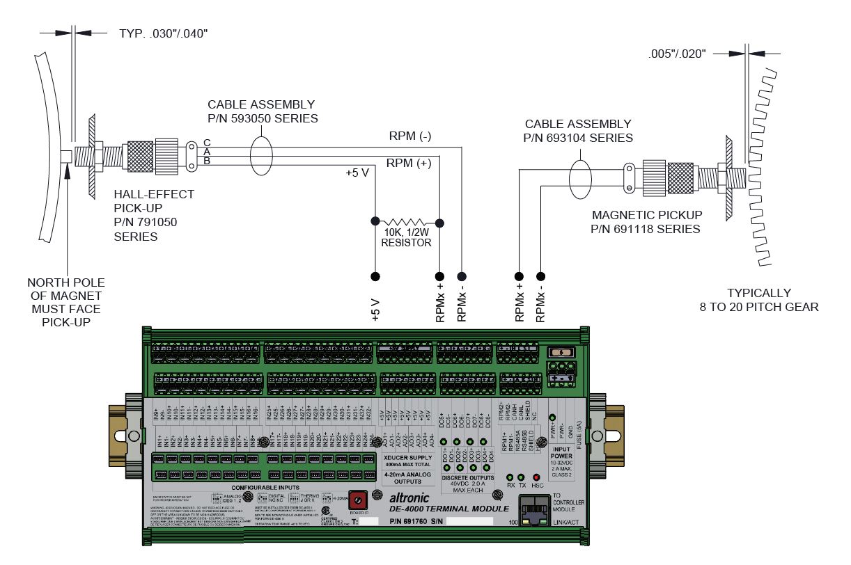
NOTE: EITHER RPM INPUT CAN ACCEPT A MAGNETIC OR HALL EFFECT PICKUP.