NGI-5000 System Installation Instructions
WARNING: DEVIATION FROM THESE INSTALLATION INSTRUCTIONS MAY LEAD TO
IMPROPER ENGINE OPERATION WHICH COULD CAUSE PERSONAL INJURY TO
OPERATORS OR OTHER NEARBY PERSONNEL
SYSTEM DESCRIPTION
The Altronic NGI-5000 DC powered ignition system is a microprocessor and computer module based capacitor discharge system. Incorporating Varispark and advanced solutions applicable to slow and medium speed, stationary engines. The system features an increase in timing accuracy from the previous crank-shaft triggered timing and maintains the ability to adjust timing with with several means to include an external 4-20mA control loop. The system is field programmable and field updatable for firmware and software. It offers web based technology to make it PC operating system agnostic, a new engine configuration tool, and direct measure secondary KV values. The NGI-5000 system consists of 4 main parts; A user interface logic module (with two high resolution screens); a Diagnostic Communications, Power Module (DCPM); a Cylinder Ignition Unit (CIU); and a new ignition coil with integrated circuits.
The logic module has two HDMI monitors built into the face of the swing open door. It offers a status screen on the top for operation status information. A bottom screen is a touch input and has all of the diagnostic feed back as well as set up screens to adjust the ignition parameters. Logic module installation and operating instructions can be found here NGI-5000 Operating Instructions Installation Instructions
A separate module, that mounts in place of the existing CPU-2000 diagnostic module, provides diagnostics, advanced communications a distributor and a power supply for the primary voltage. It’s primary linkage to the Logic module is an ethernet connection with RJ45 connectors and the original logic harness. Connections to the CIU’s are ethernet cables to each module.
A distributed architecture is used for the control of each cylinder. From the DCPM an ethernet cable is used to send the fire signals and communications to each CIU. One CIU is applied to each cylinder and has a channel per spark plug. One being the main chamber and the other being the pre-chamber. If only one spark plug per cylinder is applicable the other output channel is left disconnected. A CIU is equipped with a microprocessor for each channel for monitoring diagnostics, generating the primary output control, and has dedicated communications back to the DCPM.
Being that each CIU has two channels, there are two output MS connectors as well as one MS connector on each coil. These have several wires going between the CIU and ignition coil. They facilitate the primary voltage, logic power, and various diagnostic signals. The coils are designed to accept the standard shielded CPU-2000 coil secondary leads.
Power requirement is 24Vdc 12 ampere.
WARNING: THE IGNITION SYSTEM MUST BE CONFIGURED PRIOR TO USE ON AN
ENGINE.
MOUNTING THE NGI-5000 LOGIC MODULE
Refer to NGI-5000 Logic Module Installation Instructions
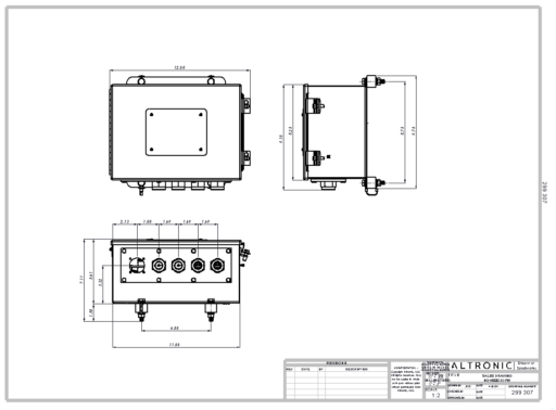
MOUNTING THE NGI-5000 Diagnostic Communications Power Module
Refer to drawing 299307 for physical dimension details. Select a mounting location
meeting the following requirements:
– On the engine.
– Within 50 ft. of the Logic Module.
– The front panel door of the DCPM should be easily accessible and free to swing
open.
– The maximum ambient temperature must not exceed 150°F. (65°C.).
The Output Module enclosure should be fastened securely to a rigid engine bracket using
the shock mounts provided.
When replacing an existing CPU-2000 system, the NGI-5000 DCPM would typically be mounted in place of the CPU-2000 diagnostic module.
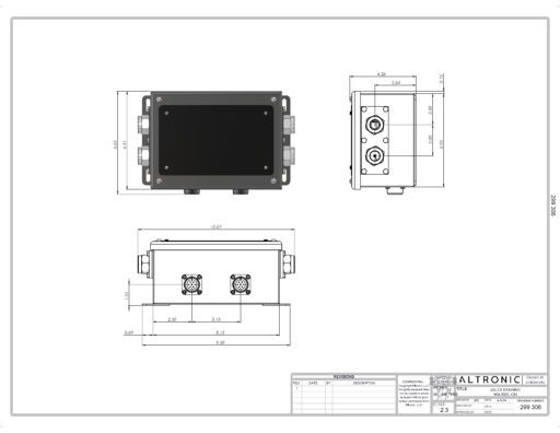
MOUNTING THE NGI-5000 Cylinder Ignition Unit
Refer to drawing 299306 for physical mounting dimension details. The mounting bolt pattern is new to the NGI-5000 system, additionally if using conduit fastened into all entry holes that is designed as an acceptable mounting method. The conduit can then be rigidly mounted to the engine. Select a mounting location meeting the following requirements:
– On the engine.
– within 3 feet of the ignition coil primary connection.
– Enclosure lids should be easily accessibly and free to remove.
– The maximum ambient temperature must not exceed 150°F (65°C).
MOUNTING THE NGI-5000 IGNITION COIL
Refer to drawing 299308 for physical mounting dimension details. Select a mounting location meeting the following requirements.
– On the engine
– within 3 feet of the cylinder ignition unit (this is dependent on the primary harnesses purchased)
– Easily accessible
– The maximum ambient temperature must not exceed 185°F (85°C.).
When replacing a CPU-2000 system, the NGI-5000 coil would typically be mounted in place of the shielded altronic shielded coil; the mounting footprint is identical to facilitate the changeover.
DCPM ELECTRICAL HOOK-UP
The power connections to the NGI-5000 system must be in accordance with the National
Electrical Code or other applicable country code.
The DCPM must have it’s own 24Vdc power connection. Although the device has an internal protective fuse (10A), an external fuse near the power source is recommended. Several entries are made using a gland plate such that the gland plate can be removed if needed to gain access and remove the DCPM. four conduit entries and one MS connector are present. The MS connector is designed to accept the CPU-2000 logic harness.
Power wiring and signal wiring must be in separate conduits and conduit entries in the DCPM to avoid undesired electrical interaction. All conduit entries are sized for a 3/4″ NPT male conduit fitting. Separate as follows:
LEFT CONDUIT ENTRY — Left bank bundle of ethernet cables
LEFT CENTER CONDUIT ENTRY — Right bank bundle of ethernet cables
RIGHT CENTER CONDUIT ENTRY — Ethernet cable from logic module
RIGHT CONDUIT ENTRY — Primary voltage cable
CIU ELECTRICAL HOOK-UP
Connection to the Cylinder Ignition Unit is simplified by using ethernet cable for the low voltage and communications, and a single 3 conductor cable to connect the primary voltage into each CIU. Power and signal wiring must be in separate conduits to avoid undesired electrical interaction.
There are four 1/2″ conduit entries for a male NPT fitting. When wiring the primary voltage there are two connectors on each CIU. This is to allow cabling to enter in on side and exit out the other to connect each CIU in a series manner
Ethernet cables will come from the DCPM in a parallel manner and each cable will come from the DCPM plug separately into each CIU.
Ethernet cables are carrying the following signals:
24VDC (+)
24VDC (-)
FIRE 1
FIRE2
RS485(+)
RS485(-)
These ethernet cables are what map the firing order, it is recommended to label each cable and maintain traceability. Place each CIU in numerical order from 1 to the engine cylinder count, then inside the DCPM map the firing order.
Additionally exiting the CIU are two MS connectors. Each one is dedicated for a coil and will be used for the main chamber spark plug and if equipped a pre-chamber spark plug.
Ethernet Cable Construction
Ethernet cables are routed through conduit from the DCPM and to each CIU. After cables have been landed in each box RJ45 plug ends will be installed.
A standard cable tool can be used to crimp the RJ45 connectors in place. It is recommended to use high quality connectors with a strain relief. LGEGPTRJ45 is one example of connector that is recommended.
There are two standards to wiring of an RJ45 ethernet connector; the “B” standard must be adhered to for proper function of the system.
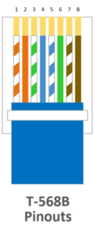
An ethernet cable tester is recommended to verify proper cable operation before being put into service.
DC POWER HOOK-UP
The power connections to the NGI-5000 must be in accordance with the National
Electrical Code or other applicable country code.
It is necessary to split the control cable and power leads of the 293030 cable in an engine
mounted junction box or conduit tee.
The junction box should have three (3) 1/2″ conduit entries:
1 ST ENTRY – Conduit fitting of 293030 series connecting cable from the Output Module.
2ND ENTRY – Two leads from a source of nominal 24 Vdc (20-32 Vdc). The negative of
the 24 Vdc supply MUST be common with engine ground. Refer to
drawing 209 120 for details of the power hookup.
3RD ENTRY – The gray jacketed control cable from the 293030 series cable connecting
to either the Diagnostic or Logic Module.
The NGI-5000 system can be powered in one of the following ways:
A. 24 volt battery with charger.
B. DC power supply capable of furnishing 24-28 Vdc.
NOTE: The negative (-) of the 24 Vdc supply MUST BE COMMON WITH ENGINE
GROUND. Engines using positive ground DC accessories or starter motors will
require a separate dedicated power supply for the NGI-5000.
PRIMARY WIRING
Wiring the primary of the coils is a purchased harness that contains 7 pin MS connectors on both ends. One cable is needed for each the main chamber and pre-chamber coils. All mounting will depend on the purchased length of the primary cable.
SECONDARY WIRING
Mount the ignition coils as close as possible to the engine spark plugs consistent with a
secure mounting and avoidance of temperatures in excess of 185°F (85°C.).
The spark plug leads should be fabricated from silicone insulated 7 mm cable with suitable
terminals and silicone spark plug boots. The use of leads with resistor spark plug boots
(Altronic series 59320x-xx) is recommended to minimize interference from emitted RFI on
the operation of other nearby electronic equipment. Another option is the use of
suppression ignition cable (Altronic part no. 503185). It is also essential to keep spark
plug leads as short as possible and in all cases not longer than 24 inches (600 mm).
Spark plug leads should be kept at least 2 inches (50 mm) away from any grounded
engine part. In deep spark plug wells, use rigid insulated extenders projecting out of the
well.
The use of a clear, silicone grease (such as Dow Corning DC-4, G.E. G-623 or GC
Electronics ZS) is recommended for all high-tension connections and boots. This material
helps seal out moisture and prevent corrosion from atmospheric sources.
COMPONENT DRAWINGS
299307 Diagnostic Communication Power Module
299 306 Cylinder Ignition Unit Dimensional Drawing
299308 Ignition Coil