SYSTEM DESCRIPTION
OVERVIEW
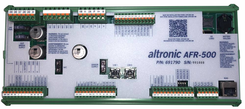
The Altronic AFR-500 is a single channel stand-alone air fuel ratio controller designed for use on carbureted natural gas-fueled engines. It employs high end precision microprocessor technology allowing for a detailed level of sophistication in control strategy, and ease of programming. Accompanying this precision control is a wide band oxygen sensor for accuracy and resolution. An innovative approach for user interface and display options are now utilized on this platform. The AFR-500 is designed for use on a variety of engines operating at or near a stoichiometric air/fuel ratio (lambda 0.95-1.00) and is ideally suited for applications with 3-way catalytic converters. The AFR-500 is designed to be mounted in the engine/compressor control panel.
A flexible output control mechanism incorporated into the AFR-500 allows for its use on most all engine applications with a single fuel gas regulator or stepper motor per bank. A heated wideband Lambda sensor “UEGO” is used in the exhaust stream to sense the actual exhaust Lambda value, and a thermocouple input determines when the proper exhaust temperature has been reached to allow for accurate air fuel ratio operation. The system fuel control valve installed in the fuel line to the carburetor is precisely adjusted under microprocessor control to maintain the correct engine air-fuel ratio. The desired air/fuel ratio can be easily adjusted by changing the control target set point by changing the internal Modbus register values from any communication capable device such as a PLC, PC, DE-4000 or touch screen display.
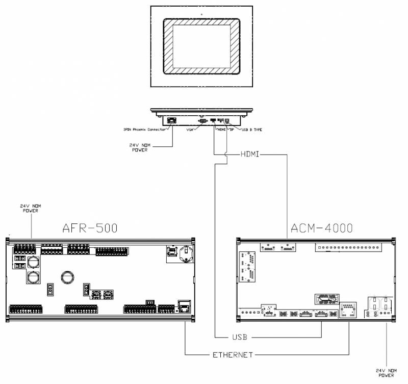
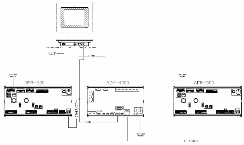
As an AFR system the AFR-500 offers the ability to be used as a single device or one unit per bank on a “V” type engine. Although in dual bank operating mode there are two AFR-500 boards, there is a single interface and system integration. In addition to the two terminal boards an ACM-4000 is recommended for connecting the units and providing display functionality.
Connecting to The System
RS485 Modbus connection
The backbone of the communication system is modbus and its associated registers. Regardless of the protocol being used, all information passed to and from the controller and its application uses the internal modbus registers. Currently there are two RS485 ports, while only one is active for modbus slave operation. Future provisions are there to allow for a modbus master port. To connect over RS485 and using the modbus protocol connect the two wires to port 1 on the controller as shown below
The other end of the two wire connection goes to any standard converter such as the BandB modem that is conventionally used with Altronic products. A PC or any other RS485 master device can then poll and interact with the AFR-500.
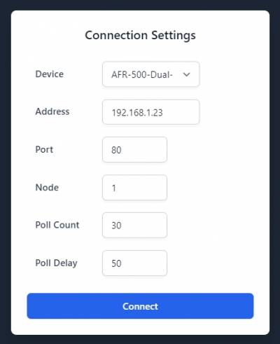
The following setting are used for the modbus protocol connection over RS485:
Ethernet Connection
As a direct connection over ethernet, an RJ-45 port is vertically mounted on the AFR-500. Using a standard ethernet cable plug one end into the AFR-500 controller, and the other end goes to a device that can send HTTP requests following the modbus/TCP or Ethernet/IP protocols. In general, the two use cases will be with the Altronic AWI application on a computer or permanently displayed on an HMI.
While a direct connection to a computer ethernet port is capable, it is recommended to utilize a USB to ethernet adapter. While using a USB to ethernet adapter it is still possible to use wireless internet. Plugging in to the native ethernet port of a computer diverts the operating system to try and use what is plugged in as the internet connection. This in turn does not allow the wireless and the ethernet port to work in conjunction with each other.
Interface options
To provide a commissioning interface and the option for a permanently mounted display there is an Altronic Web Interface (AWI) now available. How to connect and operate the AWI is available in the link below. No need to install any third part programs or deal with windows operating environments. This AWI solution is browser based, operates offline, has pre-built screens ready to go, and is customizable by the user to display the data how and where they want.
Connection Parameters
Click here for AWI CONNECTION AND INTERFACE MANUAL
Single bank display configuration:
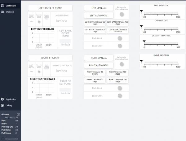
Dual bank display configuration
SYSTEM COMPONENTS
Parts from each group below are required for each installation:
AFR-500 Control Module…………………………………………………………. …..691790-1
Control Valve, 0.75“ NPT Piston-Style Stepper, <250 HP……………….. 690153-1
Control Valve, 1.5” NPT Piston-Style Stepper, <250 HP…………………690154-5
Control Valve, 1.5“ NPT Piston-Style Stepper, <500 HP………………… 690154-2
Control Valve, 1.5” NPT Piston-Style Stepper, <1000 HP……………….. 690154-1
Control Valve, 1.0“ NPT Butterfly-Style Stepper, <500 HP…………….. 690210-1
Control Valve, 2.0” NPT Butterfly-Style Stepper, <1000 HP……………. 690220-1
Control Valve, 2.5“ NPT Butterfly-Style Stepper, <1500 HP……………. 690225-1
Control Valve, 3.0” NPT Butterfly-Style Stepper, <2000 HP…………… 690230-1
Control Valve, 1.0“ NPT Fuel Pressure Control, <500 HP……………….. 690318-1
691808-1 Wideband Sensor Accessory Kit
Wideband Oxygen Sensor LSU 4.9………………………………………………….691806
Cable Assembly, Control Valve, 25 ft…..……………………………………….. 693005-1
Cable Assembly, Wideband Oxygen Sensor, 25 ft…..……………………. 693226-1
691808-2 Wideband Sensor Accessory Kit
Wideband Oxygen Sensor…………………………………………………………… 691806
Cable Assembly, Control Valve, 50 ft…………………………………………….693005-2
Cable Assembly, Wideband Oxygen Sensor, 50 ft………………………….693226-2
“K” Thermocouple Probe ……………………………………………………………. Not Included in Altronic Kit
“K” Thermocouple Ext. Wire………………………………………………………….Not Included in Altronic Kit
15” Display – Environmental Enclosure………………………………………..691767-15
8“ Display – Environmental Enclosure…………………………………………..691767-8
Make link ACM-4000 Altronic Compute Module……………………………691810-1
THEORY OF OPERATION
The primary task of the AFR-500 is to accurately control the exhaust air fuel ratio (AFR) of an engine. Control should be maintained through reasonable load and fuel BTU variations.
Three-way catalysts are used to oxidize CO and HC and to reduce NOx. These processes require high temperature and correct AFR control. Catalysts perform best for all emissions when operated near the stoichiometric AFR.
The stoichiometric AFR is the AFR at which exactly the required amount of air (Lambda) is present to completely burn all of the fuel. Because no engine can perform perfect combustion, typical emission by-products include Lambda, HC, NO, and CO even though the engine is running at stoichiometry. The stoichiometric AFR is determined by the chemical composition of the fuel, thus they are different for each fuel, or BTU rating.
(e.g., Methane => 16.9:1 and Gasoline => 14.70:1)
Pipeline natural gas Lambda 1 is typically about 17.0:1
Because the fuel type is not always known, it is often easier to specify the AFR target in terms of Lambda. Lambda is an indicator of AFR normalized to the appropriate stoichiometric AFR.
(Lambda Actual AFR/Stoichiometric AFR)
Lambda for stoichiometric combustion would be 1.0, no matter what fuel is used.
Lambda > 1 = Lean, Lambda < 1 = Rich
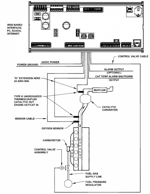
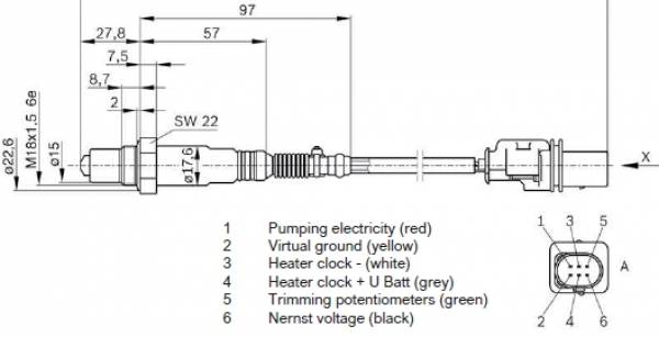
A wide band Lambda sensor (Lambda sensor) is used to provide exhaust AFR feedback to the AFR-500. This type of sensor creates an output signal used to indicate the amount of Lambda in the engine exhaust. Characteristics of the sensor include: an integrated heater circuit which can draw up to 3A, sensitivity is linear across the range of the sensor. The output signal provides a very suitable means of controlling just rich of Lambda 1.0, which is the AFR range required to obtain best catalyst efficiencies for methane-based fuels.
A type K thermocouple is used to assure that exhaust temperatures are high enough for correct operation of the system before closed loop control is enabled An additional thermocouple is used to monitor outlet temperature. The AFR-500 is designed for use on small engines where the catalyst is assumed to be close to the engine. The engine out temperature is assumed to be representative of the catalyst in temperature. The three shutdown thresholds are Engine/Cat In temperature too high, Cat Out temperature too high, and Catalyst temperature rise too high. Temperature limit setpoints are provided to create a catalyst protection shutdown capability.
An electronic valve is used to create a variable restriction between the fuel pressure regulator and the carburetor inlet. This restriction is used to adjust the effective inlet pressure seen by the carburetor and results in a mechanical adjustment of the air/fuel mixture delivered by the carburetor. A control loop adjusts the restriction by moving a spool inside the valve. An Altronic Pressure Regulator is a voice coil consisting of a permanent magnet armature and a voice coil winding. Using high resolution electronics, analog feedback provides accurate linear positioning capability. The voice coil used provides pure analog traversing for a full stroke of 0.300” with an initial dead band of 0.050“. This affords soft entry of gas, and force balancing.
The AFR-500 adjusts the actuator to maintain a specific setpoint value from the Lambda sensor. When the value is above the Lambda target voltage, the system is richer than desired, and the control valve is moved in a closing direction to further restrict fuel flow to the carburetor. Conversely, when the system is leaner than desired, and the valve position is opened to reduce the restriction of fuel flow.
Control target setpoint must be determined with the use of an exhaust analyzer to locate the operating point of lowest stack emissions. The target value is adjustable in the AFR-500 through the configuration tool and Modbus registers. The resulting system provides accurate and stable control of air/fuel ratio which results in high catalyst efficiencies and reduced stack emissions.
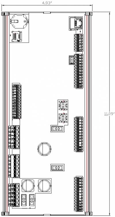
MOUNTING AND ENVIRONMENT OF THE AFR-500
Operating temperature range: -4°F to 158°F / -20°C to 70°C
Humidity specification: 0-95%, non-condensing
Mount the AFR-500 inside a control panel preferably off the engine,
in such a manner as to minimize exposure to vibration. preferably off the engine, in such a manner as to minimize exposure to vibration.
Overall mounting is straight forward as it uses DIN rail clips that are integrated into the
enclosure end caps. To remove the device there are screwdriver slots that allow
the technician to apply pressure and release one side from the DIN rail. Be sure
to mount the device so that the removal slots are accessible.
MOUNTING THE UEGO OR WIDE-BAND SENSOR
The Lambda sensor should be installed in the exhaust system between the engine and the catalytic converter and/or muffler. The mounting location should be as close to the exhaust manifold of the engine as possible. The tip of the sensor should be exposed to the unobstructed flow of the exhaust gases from all cylinders of the engine. The sensor should be mounted near, but before, the exhaust stack. Once the downstream position of the wideband Lambda sensor has been determined in the exhaust system, the bung should be mounted between 9 o’clock and 3 o’clock. Condensation buildup can destroy a sensor very quickly. Mounting the sensor between 9 o’clock and 3 o’clock protects it from water build-up at the bottom of the exhaust pipe. If there is sufficient space between the top of the exhaust pipe and other obstructions, mounting the sensor at 12 o’clock is ideal.
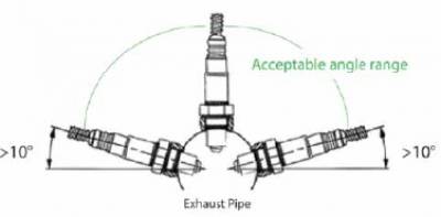
DO NOT locate the sensor in a coupling or in a location where the exhaust gas flow is uneven due to obstructions or sharp bends. The sensor location should allow easy access since periodic sensor replacement may be required in some applications. The location should not subject the exterior shell of the sensor to an ambient air temperature greater than 350°F.
Drill, tap, and spot face a hole in the exhaust pipe at the selected location. A flat, smooth-sealing surface is required to assure accurate readings since air or exhaust leaks will impact sensor operation.
New sensors are packaged with an anti-seize compound applied to the threads. There is no need to apply additional anti-seize unless reinstalling a used sensor. If required, use high temperature anti-seize very sparingly and apply only to the sensor threads. Sensors should be torqued to 28-34 lb.-ft.
MOUNTING THE K-TYPE THERMOCOUPLES
An exhaust temperature thermocouple is used to monitor the temperature of exhaust gases near the exhaust Lambda sensor. It should be mounted as close as possible to the Lambda sensor. As with the Lambda sensor, the location should be easily accessible, and the tip of the probe, which should be enclosed by a thermowell, should be surrounded by unobstructed exhaust flow. It is also necessary to insure that the probe is centered as close as possible, half way in the center of the exhaust cavity where it is mounted.
Only ungrounded thermocouple probes can be used with the AFR-500. Grounded type thermocouples will not function correctly. Resistance from either lead of the thermocouple to the probe shell should be 2 megohms or greater.
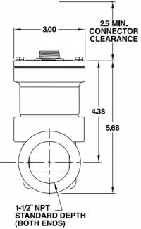
MOUNTING THE FUEL CONTROL VALVE
In order to regulate the air fuel ratio, an electronically controlled valve is connected in series between each regulator and carburetor. The valve should be installed as close to the fuel inlet of the carburetors as possible. The distance from the valve to the carburetor inlet should not exceed 12 pipe diameters in length. The valve should be installed with the control cable connector from 45 to -45 degrees.
Multiple types of fuel regulating valves are currently available, the stepper motor controlled valves are:
Altronic part number 690153-1 3/4” Fuel Control Valve\\

Altronic part number 690154-1\\
Altronic part number 690210-1\\ Altronic part number 690220-1
Altronic part number 690225-1
Altronic part number 690230-1\\
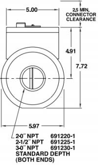
If possible, connection piping should be of the same diameter as currently in use. The threaded connection to the valve body may require the use of thread adaptors. If adaptors are used, proper plumbing procedures must be followed.
The stepper control valve is connected to the AFR-500 using the 693013-1 cable. This cable must not be run in the same conduit as the ignition primary or other Lambda sensor or thermocouple wires. A minimum distance of 4 to 6 inches should be maintained between AFR-500 wiring and other engine wiring.
ELECTRICAL HOOK-UP
POWER WIRING
The power connections to the AFR-500 must be in accordance with the National Electrical Code.
The AFR-500 is suitable for installation in Class I, Division 2 Groups C and D locations. when using a class II power supply
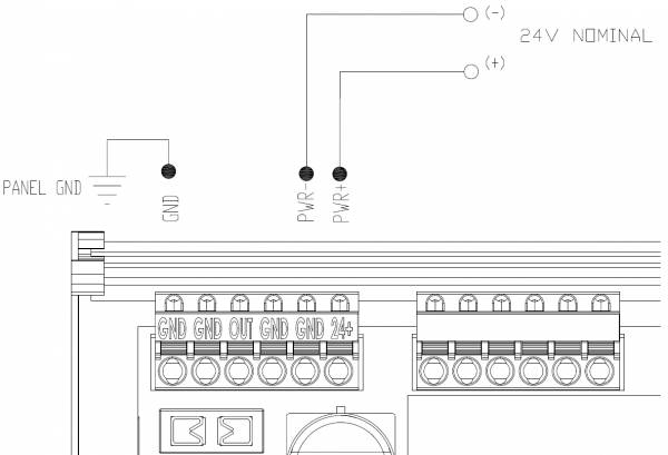
Power requirement is 24 Vdc, 5 amps maximum
An external fuse (5 amp max.) near the power source is recommended.
The AFR-500 can be powered in one of the following ways:
24 volt battery with charger (5 amp min. output)
DC power supply capable of furnishing 24 Vdc, 5 amps
Power wiring and INST wiring must be in separate conduits and conduit entries into the panel containing the AFR-500 to avoid undesired electrical interaction.
Input power supply wires (16 AWG minimum) should connect to the +24 volt and GND supply terminals of the main terminal block.
Using the 693013-x cable connected to the stepper motor routes it to the dual H-bridge outputs. Refer to the chart below for connections. An additional feature of the dual output H-bridges is that they can be utilized to drive different inductive actuators when not being used with a stepper control valve.
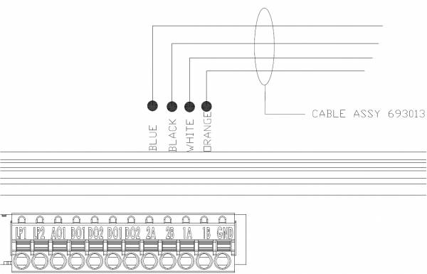
| WIRE IN CABLE | AFR-500 CONNECTION |
|---|---|
| 693013-1 PIN-B / BLUE | OUT bridge 2A |
| 693013-1 PIN-A / BLACK | OUT bridge 2B |
| 693013-1 PIN-C / WHITE | OUT bridge 1A |
| 693013-1 PIN-F / ORANGE | OUT bridge 1B |
The Lambda sensor is connected via shielded cable P/N 693226-1. This should be run in conduit only with the AFR-500 thermocouple connections. These cables should enter the panel containing the AFR-500 and connect to the terminal block “VM” through “IA” as shown in the chart below.
The cable provided is terminated with weather-tight connectors which mate to the Lambda sensors provided by Altronic. The shield wire (green wire at connector must be connected to the exhaust piping near the sensor. This shield will assist in rejecting noise from other wiring which could affect the Lambda sensor signal.
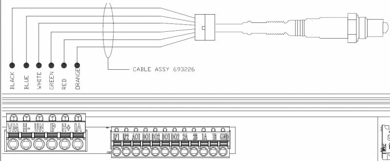
| WIRE IN CABLE | AFR-500 CONNECTION | O2 CONN PIN# |
|---|---|---|
| BLACK | VM | 2 |
| BLUE | H- | 3 |
| WHITE | UN | 6 |
| GREEN | IP | 1 |
| RED | H+ | 4 |
| ORANGE | IA | 5 |
NOTE:
The pre and post catalyst thermocouples (24 AWG min., type K extension) wires
should be run in a conduit only with the AFR-500 Lambda sensor wires. The
yellow wire should be connected to the TCK_1+ terminal and the red wire to the
TCK_1- terminal for pre-catalyst temperature monitoring. The post catalyst TC
is connected to TCK_2+ and TCK_2-.
SINGLE BANK OPERATION
SETUP
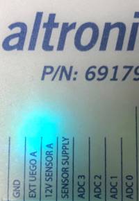
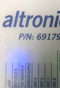
With no jumpers installed, the AFR-500 is in single bank operating mode.
This is indicated by a Turquoise LED located below the altronic P/N.
At a minimum for AFR control the following inputs and parameters are required:
- O2 set point – Target for Air/Fuel Ratio
- Wide Band O2 sensor – Provides feedback from the exhaust for system control
- Stepper Motor – Connected and functioning
- TC1 – Thermocouple to indicate when the AFR-500 should start controlling
- Default Stepper Position – Starting position for stepper motor before AFR control starts closed loop control
PARAMETERS
In all operating modes, the AFR-500 uses its modbus registers as the operating parameter list.
This allows for communication to the display, external user communication, and to the Auxiliary board in Dual Bank Mode.
All data points are stored internally in memory and upon power cycling, set up and configuration parameters are all retained.
A permanently mounted display is preferred, but the same environment can be brought up on a PC to commission the system.
O2 setpoint
The O2 setpoint is the first parameter that needs configured.

Setting the setpoint is done by entering in the value of Lambda that is the best air/fuel ratio to start the engine and operate at idle. For more detailed information about Lambda refer to THEORY OF OPERATION
The key take away is:
Lambda < 1 = Rich ——— Lambda > 1 = Lean
This will default to .95 lambda upon a new start up and is slightly rich which in most instances will not damage equipment. Running in a lean condition when not intended is a condition that can cause damage to the engine.
For a rich burn engine the typical range of running and meeting emissions will be .90 to 1.02 Lambda
NOTE: These are only recommendations and actual engine conditions will vary and the only way to accurately determine the correct emissions is to utilize an exhaust analyzer.
WIDE BAND LAMBDA SENSOR
The wide band sensor used in conjunction with the AFR-500 is the Bosch LSU 4.9. Due to the complex nature of how the sensor operates, it is not possible to use any other variant. The LSU 4.9 is a 6 wire device that interfaces with a specific controller integrated circuit and provides precise feedback on the air content left in the exhaust of the engine. There are several diagnostic feedback features, however for simplicity of the system the AFR-500 is only observing the Lambda sensor and control status. This is available through register XXXXX and can be brought out through the AWI if desired.

There are several ways in the AWI to view the O2 feedback and is covered in the Interface and connection manual
As a default the Lambda is displayed as a value and in graph form.
Stepper Motor Connected and Functioning
Altronic stepper motors are unipolar 6 wire type motors. They are unipolar such that each step is turned on to ground from the voltage source. Traditionally there were two wires that were tied to the voltage source while the other were tied to the motor steps. In the case of the AFR-500 and its versatile output driver there is no need to connect the two wires that originally were connected to a voltage source. This is all done internally.
Once the stepper motors are installed the way to tell if they are moving is to manually move them and watch the Lambda feedback to see that it adjusted in the proper direction (Rich/Lean). It is advantageous that before the stepper valves are installed, to move them manually through the AWI and watch the positioning mechanism to move.

THERMOCOUPLES
There are three thermocouples available for temperatures sensing. The inputs are designed to accept K type thermocouples only and are intended for sensing exhaust temperatures in the system. Ideally one thermocouple would measure exhaust temperature close to the exhaust manifold and senses the temperature for the health of the engine and its operating condition. Thermocouples two and three are generalized for pre and post catalyst temperature monitoring.
TCK1 is linked to the start up temperature and is critical to have an input connected. Currently the indication for the system to start closed loop control is based on exhaust temperature. When the temperature is above 650° F the AFR-500 system goes into closed loop control. One condition that also needs to be met is that the Auto control is active from the user selection.
TCK2 would be best utilized to measure the inlet temperature to the catalyst
TCK3 would be best utilized to measure the outlet temperature of the catalyst
There is an internal parameter that allows for differential temperature monitoring and it takes the absolute value of the different from TCK3 to TCK2. Therefore being absolute it will show a negative sign. In most cases once the catalyst has come up to temperature the outlet will be 30° to 60° higher due to the exothermic reaction in the catalyst. Until the catalyst is up to operating temperature you will notice that the inlet is hotter than the outlet.
Default Stepper Position
A default stepper position provides a starting point for the stepper valve when the engine is off and waiting to be started. It will also continue to hold this default position while the engine is warming up. Once the engine reaches above 650°F on TCK1 the temperature condition to move into auto mode has been satisfied. As long as the AFR-500 is in auto mode when the temperature condition is met then the stepper valve will start to move into closed loop control.
The stepper motors in conjunction with the AFR-500 controller have a range of 2000 steps where 1000 steps is in the middle. With the default PID control algorithm for O2 control the valve can move fully open to fully closed in less than 5 seconds. This is heavily dependent on the gap between the set point and the actual position. A default stepper position of around 1000 steps would be an okay place to start. As with most altronic products that drive our stepper valves, the steps are inverse to the actual stepper position.
Stepper Position 2000 = Fully closed Stepper Position 1000 = Middle Stepper Position 0 = Fully open
After the engine has been shut down the method for the AFR-500 to know to stop actively controlling is based on the temperature on TCK1. As the temperature falls when the engine is off there is a hysteresis of 50°F and therefore will stop actively controlling below 600°F. Below the low threshold the system will reset and return the stepper valves to the default position.
Auto/Manual Selection

This mode selection switches the system between manual and automatic closed loop control of the air/fuel ratio. In manual mode the stepper will stay in its current position and will not move unless commanded by the user. The increase and decrease button commands of the stepper will only work in manual mode, and is mostly used during commissioning of the engine to find the correct stepper valve position for given load conditions. This is described below in the start up section.
When switching into Auto control, as long as the the temperature on TCK1 is above 650°F, there will be a smooth bumpless transition for the system to start controlling. There is also an indicator register that allows for feedback that the unit is in auto mode. The default configuration is a blue LED that will illuminate on the AWI for Auto mode and is grey when in manual mode.

F1 START
F1 start comes from the original EPC product line and has the same nomenclature for familiarity. The purpose of the F1 start is to be able to place the stepped back into default mode manually.

As described earlier, the way the system knows when to control based on engine operation is the exhaust temperature on TCK1. After the engine is above the 650°F threshold and then shut down, the steppers are going to open all of the way (0 steps). This is due to no exhaust being generated, the control of the AFR-500 will indicate that it is too lean, and consequently the stepper valves will open to try and richen the air/fuel mixture.
DUAL BANK OPERATION
SYSTEM OVERVIEW
When operating on a “V” engine, or also considered as a dual bank engine, the system requires two AFR-500 boards, and at minimum a way for the system to be commissioned with a user interface. By configuring each AFR board with a jumper wire as described below, the two boards work in unison to provide a single AFR system. It then has the capability for expanded inputs and outputs, as well as fully configurable independent or shared operation on each bank of the engine.
SETUP
To place the system in dual bank mode, each board needs a jumper applied using the digital inputs.
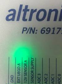
Jumper GND – DI4 = Primary Mode Primary Mode Is indicated by a GREEN LED located below the Altronic P/N on the label
Jumper +5V – AD3 = Auxiliary Mode Auxiliary Mode is indicated by a BLUE LED located below the Altronic P/N on the label
Once the AFR-500 boards themselves are placed into dual bank mode, an ACM-4000 is required to route all of the communication between the two boards, provide display capability, and interface with a PC or third party device over ethernet.
For connecting the ACM-4000 and the AFR-500 this information can be found at ACM-4000 Documentation
CONFIGURATION
The AFR-500 uses non-volatile memory to store its parameters, and utilizes the modbust data structure to transfer information between the boards. Configuration is done in the same way as a single bank. Registers for the primary are < 500 Auxiliary Register are > 500.
When looking at the list of parameters there are:
PRIMARY 00XXX, 10XXX, 30XXX, 40XXX
AUXILIARY 005XX, 105XX, 305XX, 405XX
It is highly recommended to use the Primary for the LEFT bank and the Auxiliary for the RIGHT bank
This helps to keep information consistent and standard. However it is best to refer to the AFR system and primary and auxiliary since left bank and right bank could mixed up without the user knowing this.
SHARED OR UNSHARED SENSOR INPUTS
Dual bank operation provides for the expansion of all the IO since there is now an additional terminal board. The default configuration is to have each input mapped to use an external sensor. Each board will then read its own sensors and operate under control to perform the adjustments to the output stepper valve.
There may be more often times that there is one sensor, but it needs to control or provide input information to both boards. For example there may only be one exhaust output thermocouple, and adding an additional thermocouple port in the exhaust is a cumbersome task. It also is necessary to share a sensor so the system starts and stops based off the same input and other situations similar to this.
The AFR-500 dual bank system has the option to share sensor information. When sharing information between the two boards, it will always be from the Primary to the Auxiliary. It is not possible to share information from the Auxiliary.
The current list of shared information:
- TCK1
- TCK2
- TCK3
- Exhaust Lambda Input
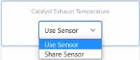
After setting a display element on the dashboard as the correct channel for sharing a sensor input, set it as a drop down menu. Now in the AWI it is possible to use the sensor input or share the data to the Auxiliary. When selecting “Use Sensor” the Auxiliary board will use its own sensor input. Alternatively selecting “Share Sensor” directs the Auxiliary to use the data from the sensor input on the primary.
O2 SET POINT BIAS MAPPING
The O2 set point is entered in Lambda and provides the target for the system to control to. There are applications where a single O2 set point will not be adequate enough to keep the engine in compliance across the entire load range from start up to full load. For these instances there are offset maps available to bias the base O2 set point, and are tied to four fully adaptable analog inputs. Each analog input has its own mapping table, and will sum together for one final offset to the O2 set point. They each allow for custom units, scaling, and labels. In addition to this there are some unique features for dual bank on how the information of the tables can be shared.
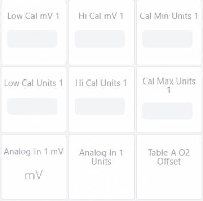
In general when creating a mapping table of any kind, there must be an “X” and “Y” coordinate (X,Y). In the case of building O2 offset mapping “X” is the input being measured and “Y” is the amount of offset to apply to the base O2 set point. It is possible to have up to 10 mapping points in one table, but not necessary and any time there is a zero entered the table will stop at the last point with valid values. Entering in a value that is not in order for the “X” input part of the table will stop at the last point with valid values. Additionally point to point is linearized as opposed to a step increase where the output offset is flat until the next point.

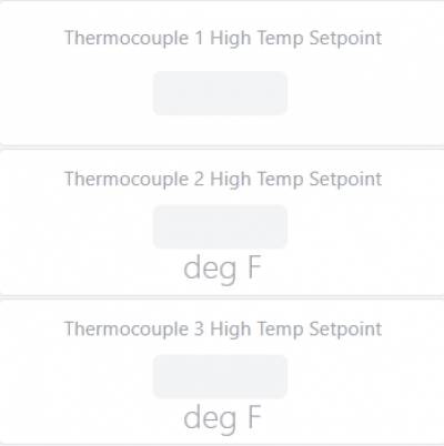
THERMOCOUPLE ALARMS
All of the thermocouple inputs have an alarm set point that is configurable. When using the dual bank system this includes the thermocouples on the auxiliary board. Additionally there is an alarm for the differential of thermocouple 3 minus thermocouple 2 for critical safety of the catalyst.
In conjunction with the alarm set points are three different type of alarm indicators.
Non-latching registers that when mapped to the AWI appear as an LED and turn off after the fault condition has cleared
Latching registers that when mapped to the AWI will appear as an LED and stay on even after the thermocouple is no longer in the fault condition
A digital output signal attached to LS Digital Output 1 that latches on a fault condition
To clear all of the alarms, regardless of a single or dual bank system, there is one ALARM ACKNOWLEDGE register.

PRE-START INSTALLATION CHECKLIST
Before applying power to the AFR-500:
A. Measure the power supply voltage to assure voltage is within limits (18- 32V or 24V nom). Leave unit unpowered.
B. With the main terminal block disengaged, measure voltage between yellow and red thermocouple wires. The voltage should be 0.80-1.50mV for temperatures of 60-100°F. This verifies that thermocouple wires are terminated. If engine has been running, measurements will be higher, reflecting higher actual temperatures.
C. With the terminal block still disengaged, measure resistance between the red wire and the still-connected earth ground terminal. Resistance should be very high or open circuit. Repeat measurement between yellow wire and earth ground. This verifies that thermocouples are ungrounded and that wires are not shorted in conduit.
After installation with the AFR-500 powered up and the engine not running:
A. A compatible User Interface may be connected via the ethernet port.
B. AWI screen for exhaust temperatures should indicate ambient temperatures.
C. Stepper Control valve operation should be verified by creating a start position command. This can be done from the User Interface or by pressing F1 Start. Visual confirmation can easily be done if the valve is not yet fully installed in the fuel line. During the start position activity, the stepper valve plunger should be fully retracted, then positioned near the middle of its travel. No movement, erratic movement, or movement in the wrong direction will result from incorrect wiring of the stepper cables.
D. Configure catalyst protection thresholds. Reasonable value ranges should be configured based on the recommendations of the catalyst manufacturer. This can be done by sending the values to the Modbus registers list registers for each successive setup parameter:
Exh Temp Hi = (1000 to 1250°F) Cat Out Hi = (1100 to 1250°F) Cat Rise Hi = (100 to 300°F)
When all of these checks have been made successfully, move on to the Start- Up Procedure.
START-UP PROCEDURE
Before starting engine:
- Check for fuel leaks where the fuel line was modified.
- Verify that catalyst over-temp thermocouples and thresholds are in place and functional according to catalyst provider requirements and recommendations.
- Be sure that the power screw adjustments on carburetors are fully open or fully rich. If these adjustments are not fully open, the control range of the stepper control valve will be limited.
- If the alarm outputs of the AFR-500 are being used, temporarily disconnector override these signals so that an alarm indication will not shut down the engine during setup.
- Verify that the catalyst protection output is wired and functional to cause a shutdown in an over temperature condition.
- F. Ground Digital Input Terminal 3 or send a Modbus command to Modbus register 40081. If a user interface is used Press F1, then press START POS on the AFR
- 500 interface to reset stepper position and enable the warm-up delay.
- G. Place AFR-500 controller in manual mode by pressing appropriate key on the User interface device or writing to Modbus register 40073
- H. Start and warm-up engine.
With the engine running:
- Load engine to desired operating point.
- Verify that the exhaust temperature data screen is displaying reasonable values, and that the temperatures exceed 650°F.
- Enable automatic control from an optional User interface device by pressing the AUTO key or writing to Modbus register 40073. The unit should begin adjusting the fuel control valve, trying to control the engine air/fuel ratio. Use any diagnostic warnings which may occur to trouble-shoot the system. A Rich or Lean limit error is a good indication that the pressure regulator may need to be adjusted.
- Once the unit has gained control of the engine adjust the fuel pressure regulators until the AFR-500 is controlling with the stepper valve positions near 1000 steps. This is approximately the middle of the valve’s control range.
Fine tune the control setpoints:
- Using an exhaust analyzer, determine the Lambda set-point value which results in the best emission performance. This can be done by adjusting the Lambda target value in Modbus 40036 from an optional User interface or setup device. Alternatively, manual mode can be used to adjust the control valves to the positions which give the best emissions performance. The Lambda target value should be adjusted to match the actual sensor measured value displayed in Modbus register 30018.
- The control gain rate and default stepper positions can also be adjusted via the appropriate Modbus registers, however, the default values represent the best typical values for these parameters.
Once the system is controlling at the best emissions point, the alarm output can be re-enabled.
The AFR-500 setup is now complete; the unit should be controlling the engine.
AFR-500 MODBUS REGISTER LIST
The 10xxx registers are read-only binary and support Modbus standard function 1. These registers are read in multiples of 8 (1 byte) addressed at each 8 bit boundary (10001-10008, etc.). A single Boolean read from registers 10001 to 10064 can be made which will return all 64 values as a group of 8 bytes.
| Register | Label | Temporary Label | ReadOnly / ReadWrite Type |
|---|---|---|---|
| 10001 | save position | ReadOnly BOOL | |
| 10002 | low supply voltage | ReadOnly BOOL | |
| 10003 | Current State | ReadOnly BOOL | |
| 10004 | Control Loop Mode | ReadOnly BOOL | |
| 10005 | Spare | Position Control Winning Status | ReadOnly BOOL |
| 10006 | Spare | Pressure Control Winning Status | ReadOnly BOOL |
| 10007 | Spare | Exhaust O2 Control Winning Status | ReadOnly BOOL |
| 10008 | Automatic Control Active | ReadOnly BOOL | |
| 10009 | Getting Richer | ReadOnly BOOL | |
| 10010 | Very Rich | ReadOnly BOOL | |
| 10011 | Rich | ReadOnly BOOL | |
| 10012 | ON TARGET | ReadOnly BOOL | |
| 10013 | Lean | ReadOnly BOOL | |
| 10014 | Very Lean | ReadOnly BOOL | |
| 10015 | Getting Leaner | ReadOnly BOOL | |
| 10016 | Lean Limit | ReadOnly BOOL | |
| 10017 | Rich Limit | ReadOnly BOOL | |
| 10018 | Stepper Resetting | ReadOnly BOOL | |
| 10019 | Reserved | ReadOnly BOOL | |
| 10020 | Catalyst In High Temperature Alarm | TC CAT IN HiTemp Alarm | ReadOnly BOOL |
| 10021 | Catalyst Out High Temperature Alarm | TC CAT OUT HiTemp Alarm | ReadOnly BOOL |
| 10022 | Catalyst Delta High Temperature Alarm | TC CAT HiDelta Alarm | ReadOnly BOOL |
| 10023 | Spare | ReadOnly BOOL | |
| 10024 | Spare | ReadOnly BOOL | |
| 10505 | Spare | ReadOnly BOOL | |
| 10506 | low supply voltage | ReadOnly BOOL | |
| 10507 | Current State | ReadOnly BOOL | |
| 10508 | Spare | ReadOnly BOOL | |
| 10509 | Spare | ReadOnly BOOL | |
| 10510 | Spare | ReadOnly BOOL | |
| 10511 | Spare | ReadOnly BOOL | |
| 10512 | Automatic Control Active | ReadOnly BOOL | |
| 10513 | Getting Richer | ReadOnly BOOL | |
| 10514 | Very Rich | ReadOnly BOOL | |
| 10515 | Rich | ReadOnly BOOL | |
| 10516 | ON TARGET | ReadOnly BOOL | |
| 10517 | Lean | ReadOnly BOOL | |
| 10518 | Very Lean | ReadOnly BOOL | |
| 10519 | Getting Leaner | ReadOnly BOOL | |
| 10520 | Lean Limit | ReadOnly BOOL | |
| 10521 | Rich Limit | ReadOnly BOOL | |
| 10522 | Stepper Resetting | ReadOnly BOOL | |
| 10523 | Spare | ReadOnly BOOL | |
| 10524 | Spare | ReadOnly BOOL | |
| 10525 | Spare | ReadOnly BOOL | |
| 10526 | Spare | ReadOnly BOOL | |
| 10527 | Spare | ReadOnly BOOL | |
| 10528 | Spare | ReadOnly BOOL | |
| 11000 | Discrete In 1 | ReadOnly BOOL | |
| 11001 | Discrete In 2 | ReadOnly BOOL | |
| 11002 | Discrete In 3 | ReadOnly BOOL | |
| 11003 | Discrete In 4 | ReadOnly BOOL |
The 30xxx registers are read-only, 16 bit, analog values. The Modbus standard function 4 is supported.
| Register | Label | Temporary Label | ReadOnly / ReadWrite | Type | Factor | Units | Min | Max |
|---|---|---|---|---|---|---|---|---|
| 30001 | Input 1 Bit Mirror | Input Bit Mirror 10016 to 10001 | ReadOnly | UINT16 | ||||
| 30002 | Input 2 Bit Mirror | Input Bit Mirror 10032 to 10017 | ReadOnly | UINT16 | ||||
| 30003 | Input 3 Bit Mirror | Input Bit Mirror 10048 to 10033 | ReadOnly | UINT16 | ||||
| 30004 | Input 4 Bit Mirror | Input Bit Mirror 10064 to 10049 | ReadOnly | UINT16 | ||||
| 30005 | Input 5 Bit Mirror | Input Bit Mirror 10080 to 10063 | ReadOnly | UINT16 | ||||
| 30006 | Input 6 Bit Mirror | Input Bit Mirror 10096 to 10081 | ReadOnly | UINT16 | ||||
| 30007 | Input 7 Bit Mirror | Input Bit Mirror 10112 to 10097 | ReadOnly | UINT16 | ||||
| 30008 | Input 8 Bit Mirror | Input Bit Mirror 10128 to 10113 | ReadOnly | UINT16 | ||||
| 30009 | SUPPLY INPUT VOLTAGE | ReadOnly | UINT16 | 0.001 | Volts | |||
| 30010 | Engine Speed | ReadOnly | UINT16 | rpm | ||||
| 30011 | EXH TEMP Catalyst | ReadOnly | INT16 | 0.1 | deg F | |||
| 30012 | Catalyst Exhaust Temperature | ReadOnly | INT16 | 0.1 | deg F | |||
| 30013 | Catalyst Outlet Temperature | ReadOnly | INT16 | 0.1 | deg F | |||
| 30014 | Catalyst Temperature Rise | ReadOnly | INT16 | 0.1 | deg F | |||
| 30015 | Spare | ReadOnly | UINT16 | |||||
| 30016 | Spare | ReadOnly | UINT16 | |||||
| 30017 | CJ125 Status | ReadOnly | UINT16 | |||||
| 30018 | Exhaust Lambda Input | ReadOnly | UINT16 | 0.001 | lambda | |||
| 30019 | Exhaust Lambda Control | ReadOnly | UINT16 | counts | ||||
| 30020 | Current Stepper Position | ReadOnly | UINT16 | |||||
| 30501 | Aux Input 1 Bit Mirror | Input Bit Mirror 10016 to 10001 | ReadOnly | UINT16 | ||||
| 30502 | Aux Input 2 Bit Mirror | Input Bit Mirror 10032 to 10017 | ReadOnly | UINT16 | ||||
| 30503 | Aux Input 3 Bit Mirror | Input Bit Mirror 10048 to 10033 | ReadOnly | UINT16 | ||||
| 30504 | Aux Input 4 Bit Mirror | Input Bit Mirror 10064 to 10049 | ReadOnly | UINT16 | ||||
| 30505 | Input 5 Bit Mirror | Input Bit Mirror 10080 to 10063 | ReadOnly | UINT16 | ||||
| 30506 | Input 6 Bit Mirror | Input Bit Mirror 10096 to 10081 | ReadOnly | UINT16 | ||||
| 30507 | Input 7 Bit Mirror | Input Bit Mirror 10112 to 10097 | ReadOnly | UINT16 | ||||
| 30508 | Input 8 Bit Mirror | Input Bit Mirror 10128 to 10113 | ReadOnly | UINT16 | ||||
| 30509 | SUPPLY INPUT VOLTAGE | ReadOnly | UINT16 | 0.001 | Volts | |||
| 30510 | Engine Speed | ReadOnly | UINT16 | rpm | ||||
| 30511 | Aux EXH TEMP Catalyst | ReadOnly | INT16 | 0.1 | deg F | |||
| 30512 | Catalyst Exhaust Temperature | ReadOnly | INT16 | 0.1 | deg F | |||
| 30513 | Catalyst Outlet Temperature | ReadOnly | INT16 | 0.1 | deg F | |||
| 30514 | Catalyst Temperature Rise | ReadOnly | INT16 | 0.1 | deg F | |||
| 30515 | Spare | ReadOnly | UINT16 | |||||
| 30516 | Spare | ReadOnly | UINT16 | |||||
| 30517 | CJ125 Status | ReadOnly | UINT16 | |||||
| 30518 | Exhaust Lambda Input | ReadOnly | UINT16 | 0.001 | lambda | |||
| 30519 | Exhaust Lambda Control | ReadOnly | UINT16 | counts | ||||
| 30520 | Current Stepper Position | ReadOnly | UINT16 | |||||
| 31000 | VR input 1 | ReadOnly | UINT16 | Frequency | ||||
| 31001 | VR input 2 | ReadOnly | UINT16 | ADC Counts | 0 | 4095 | ||
| 31002 | ANALOG_IN_1 | ReadOnly | UINT16 | ADC Counts | 0 | 4095 | ||
| 31003 | ANALOG_IN_2 | ReadOnly | UINT16 | ADC Counts | 0 | 4095 | ||
| 31004 | ANALOG_IN_3 | ReadOnly | UINT16 | ADC Counts | 0 | 4095 | ||
| 31005 | ANALOG_IN_4 | ReadOnly | UINT16 | ADC Counts | 0 | 4095 | ||
| 31006 | PGA_ADC_0 | ReadOnly | UINT16 | ADC Counts | 0 | 4095 | ||
| 31007 | PGA_ADC_1 | ReadOnly | UINT16 | ADC Counts | 0 | 4095 | ||
| 31008 | PGA_ADC_2 | ReadOnly | UINT16 | ADC Counts | 0 | 4095 | ||
| 31009 | PGA_ADC_3 | ReadOnly | UINT16 | ADC Counts | 0 | 4095 | ||
| 31010 | 5V Rail Sense | 5V Rail Sense | ReadOnly | UINT16 | ADC Counts | 0 | 4095 | |
| 31011 | 3V Rail Sense | 3V Rail Sense | ReadOnly | UINT16 | ADC Counts | 0 | 4095 | |
| 31012 | Sensor Supply Voltage | Sensor Supply Voltage | ReadOnly | UINT16 | ADC Counts | 0 | 4095 | |
| 31013 | 12V fuse B | 12V fuse A | ReadOnly | UINT16 | ADC Counts | 0 | 4095 | |
| 31014 | 24V sense | 24V sense | ReadOnly | UINT16 | ADC Counts | 0 | 4095 |
The 40xxx registers are read/write, 16-bit, analog values and they support the Modbus standard functions 3, 6 and 16. These registers may have new values written to them in order to make setpoint adjustments from a remote location.
| Register | Label | Temporary Label | ReadOnly / ReadWrite | Type | Config Export | Factor | Offset | Units | Min | Max |
|---|---|---|---|---|---|---|---|---|---|---|
| 40001 | Spare | Engine RPM | ReadOnly | UINT16 | rpm | |||||
| 40002 | Spare | Manifold Pressure | ReadOnly | INT16 | psi | |||||
| 40003 | Spare | Crankcase Pressure | ReadOnly | INT16 | 0.01 | in Wc | ||||
| 40004 | Spare | Fuel Valve Input Signal | ReadOnly | UINT16 | ||||||
| 40005 | Spare | Current State | ReadOnly | UINT16 | ||||||
| 40006 | Spare | Control Loop Mode | ReadOnly | UINT16 | ||||||
| 40007 | Spare | Catalyst Exhaust Temp | ReadOnly | INT16 | 0.1 | deg F | ||||
| 40008 | Spare | Catalyst Outlet Temp | ReadOnly | INT16 | 0.1 | deg F | ||||
| 40009 | Spare | Position Input | ReadOnly | UINT16 | percent | |||||
| 40010 | Spare | Position Output | ReadOnly | UINT16 | 0.01 | percent | ||||
| 40011 | Spare | Position Control Winning Status | ReadOnly | UINT16 | ||||||
| 40012 | Spare | Pressure Input | ReadOnly | INT16 | 0.01 | in Wc | ||||
| 40013 | Spare | Pressure Output | ReadOnly | UINT16 | 0.01 | percent | ||||
| 40014 | Spare | Pressure Control Winning Status | ReadOnly | UINT16 | ||||||
| 40015 | Spare | Exhaust O2 Input | ReadOnly | UINT16 | 0.001 | lambda | ||||
| 40016 | Spare | Exhaust O2 Control Output | ReadOnly | UINT16 | counts | |||||
| 40017 | Spare | Exhaust O2 Control Winning Status | ReadOnly | UINT16 | ||||||
| 40018 | Solenoid | Solenoid | ReadOnly | UINT16 | ||||||
| 40019 | Output Mode | ReadWrite | UINT16 | Export | ||||||
| 40020 | Modbus Node Number | ReadWrite | UINT16 | Export | ||||||
| 40021 | Number of Flywheel Teeth | ReadWrite | UINT16 | Export | 1 | 500 | ||||
| 40022 | Spare | Running RPM for Valve Position | ReadWrite | UINT16 | Export | |||||
| 40023 | Spare | Load RPM for CCG Valve Open | ReadWrite | UINT16 | Export | |||||
| 40024 | Spare | Position Setpoint (starting) | ReadWrite | UINT16 | Export | percent | 0 | 100 | ||
| 40025 | Spare | Position Setpoint (running) | ReadWrite | UINT16 | Export | percent | 0 | 100 | ||
| 40026 | Spare | Position Kp | ReadWrite | UINT16 | Export | 0.01 | ||||
| 40027 | Spare | Position Ki | ReadWrite | UINT16 | Export | 0.01 | ||||
| 40028 | Spare | Position Kd | ReadWrite | UINT16 | Export | 0.01 | ||||
| 40029 | APR-1 Pressure Setpoint | ReadOnly | INT16 | Export | 0.01 | in Wc | ||||
| 40030 | APR-1 Pressure Kp | ReadWrite | UINT16 | Export | 0.01 | |||||
| 40031 | APR-1 Pressure Ki | ReadWrite | UINT16 | Export | 0.01 | |||||
| 40032 | APR-1 Pressure Kd | ReadWrite | UINT16 | Export | 0.01 | |||||
| 40033 | Spare | Position Raw Counts | ReadOnly | UINT16 | counts | 0 | 4095 | |||
| 40034 | Spare | |||||||||
| 40035 | Spare | Max position counts | ReadWrite | UINT16 | counts | 0 | 4095 | |||
| 40036 | Exhaust Lambda Setpoint | ReadWrite | UINT16 | Export | 0.001 | lambda | ||||
| 40037 | Exhaust Lambda Kp | ReadWrite | UINT16 | Export | 0.01 | |||||
| 40038 | Exhaust Lambda Ki | ReadWrite | UINT16 | Export | 0.01 | |||||
| 40039 | Exhaust Lambda Kd | ReadWrite | UINT16 | Export | 0.01 | |||||
| 40040 | Spare | Open Loop MAP (psi) 1 | ReadWrite | INT16 | Export | 0.01 | psi | |||
| 40041 | Spare | Open Loop MAP (psi) 2 | ReadWrite | INT16 | Export | 0.01 | psi | |||
| 40042 | Spare | Open Loop MAP (psi) 3 | ReadWrite | INT16 | Export | 0.01 | psi | |||
| 40043 | Spare | Open Loop MAP (psi) 4 | ReadWrite | INT16 | Export | 0.01 | psi | |||
| 40044 | Spare | Open Loop MAP (psi) 5 | ReadWrite | INT16 | Export | 0.01 | psi | |||
| 40045 | Spare | Open Loop MAP (psi) 6 | ReadWrite | INT16 | Export | 0.01 | psi | |||
| 40046 | Spare | Open Loop MAP (psi) 7 | ReadWrite | INT16 | Export | 0.01 | psi | |||
| 40047 | Spare | Open Loop MAP (psi) 8 | ReadWrite | INT16 | Export | 0.01 | psi | |||
| 40048 | Spare | Open Loop MAP (psi) 9 | ReadWrite | INT16 | Export | 0.01 | psi | |||
| 40049 | Spare | Open Loop MAP (psi) 10 | ReadWrite | INT16 | Export | 0.01 | psi | |||
| 40050 | Spare | Open Loop in Wc SP 1 | ReadWrite | INT16 | Export | 0.01 | in Wc | |||
| 40051 | Spare | Open Loop in Wc SP 2 | ReadWrite | INT16 | Export | 0.01 | in Wc | |||
| 40052 | Spare | Open Loop in Wc SP 3 | ReadWrite | INT16 | Export | 0.01 | in Wc | |||
| 40053 | Spare | Open Loop in Wc SP 4 | ReadWrite | INT16 | Export | 0.01 | in Wc | |||
| 40054 | Spare | Open Loop in Wc SP 5 | ReadWrite | INT16 | Export | 0.01 | in Wc | |||
| 40055 | Spare | Open Loop in Wc SP 6 | ReadWrite | INT16 | Export | 0.01 | in Wc | |||
| 40056 | Spare | Open Loop in Wc SP 7 | ReadWrite | INT16 | Export | 0.01 | in Wc | |||
| 40057 | Spare | Open Loop in Wc SP 8 | ReadWrite | INT16 | Export | 0.01 | in Wc | |||
| 40058 | Spare | Open Loop in Wc SP 9 | ReadWrite | INT16 | Export | 0.01 | in Wc | |||
| 40059 | Spare | Open Loop in Wc SP 10 | ReadWrite | INT16 | Export | 0.01 | in Wc | |||
| 40060 | Spare | Closed Loop O2 Target 1 | ReadWrite | UINT16 | Export | 0.01 | Lambda | |||
| 40061 | Spare | Closed Loop O2 Target 2 | ReadWrite | UINT16 | Export | 0.01 | Lambda | |||
| 40062 | Spare | Closed Loop O2 Target 3 | ReadWrite | UINT16 | Export | 0.01 | Lambda | |||
| 40063 | Spare | Closed Loop O2 Target 4 | ReadWrite | UINT16 | Export | 0.01 | Lambda | |||
| 40064 | Spare | Closed Loop O2 Target 5 | ReadWrite | UINT16 | Export | 0.01 | Lambda | |||
| 40065 | Spare | Closed Loop O2 Target 6 | ReadWrite | UINT16 | Export | 0.01 | Lambda | |||
| 40066 | Spare | Closed Loop O2 Target 7 | ReadWrite | UINT16 | Export | 0.01 | Lambda | |||
| 40067 | Spare | Closed Loop O2 Target 8 | ReadWrite | UINT16 | Export | 0.01 | Lambda | |||
| 40068 | Spare | Closed Loop O2 Target 9 | ReadWrite | UINT16 | Export | 0.01 | Lambda | |||
| 40069 | Spare | Closed Loop O2 Target 10 | ReadWrite | UINT16 | Export | 0.01 | Lambda | |||
| 40070 | Spare | Calibrate Pressure Input | ReadWrite | UINT16 | 0 | 1 | ||||
| 40071 | Spare | Manual Increase Pressure Setpoint | ReadWrite | UINT16 | 0 | 1 | ||||
| 40072 | Spare | Manual Decrease Pressure Setpoint | ReadWrite | UINT16 | 0 | 1 | ||||
| 40073 | MANUAL/AUTOMATIC | ReadWrite | UINT16 | Export | 0 | 1 | ||||
| 40074 | Air Fuel Ratio Target Range | ReadWrite | UINT16 | Export | 1 | 4 | ||||
| 40075 | Manual Increase 25 steps | ReadWrite | UINT16 | 0 | 1 | |||||
| 40076 | Manual Decrease 25 steps | ReadWrite | UINT16 | 0 | 1 | |||||
| 40077 | Manual Increase 100 steps | ReadWrite | UINT16 | 0 | 1 | |||||
| 40078 | Manual Decrease 100 steps | ReadWrite | UINT16 | 0 | 1 | |||||
| 40079 | Default Stepper Position | ReadWrite | UINT16 | Export | Steps | 0 | 1700 | |||
| 40080 | Spare | Current Stepper Position | ReadOnly | UINT16 | Steps | |||||
| 40081 | F1 Start write 1 | ReadWrite | UINT16 | 0 | 1 | |||||
| 40082 | Spare | Catalyst Inlet Temp | ReadOnly | INT16 | 0.1 | deg F | ||||
| 40083 | Spare | CJ125 Status | ReadOnly | UINT16 | ||||||
| 40084 | Spare | TC ENGOUT HI PSD | ReadWrite | UINT16 | Export | |||||
| 40085 | Catalyst Input High Setpoint | ReadWrite | UINT16 | Export | deg F | |||||
| 40086 | Catalyst Output High Setpoint | ReadWrite | UINT16 | Export | deg F | |||||
| 40087 | Catalyst Delta High Setpoint | ReadWrite | UINT16 | Export | deg F | |||||
| 40088 | Alarm Acknowledge | ReadWrite | UINT16 | |||||||
| 40089 | Spare | CATALYST TEMP RISE | ReadOnly | INT16 | 0.1 | deg F | ||||
| 40090 | Spare | Lean Limit | ReadOnly | UINT16 | ||||||
| 40091 | Spare | Rich Limit | ReadOnly | UINT16 | ||||||
| 40092 | Spare | Auto Control Active | ReadOnly | UINT16 | ||||||
| 40093 | Spare | Stepper Resetting | ReadOnly | UINT16 | ||||||
| 40094 | Spare | TC ENG HiTemp Alarm | ReadOnly | INT16 | ||||||
| 40095 | Spare | TC CAT IN HiTemp Alarm | ReadOnly | INT16 | ||||||
| 40096 | Spare | TC CAT OUT HiTemp Alarm | ReadOnly | INT16 | ||||||
| 40097 | Spare | TC CAT HiDelta Alarm | ReadOnly | INT16 | ||||||
| 40098 | Heater On Temperature Setpoint | ReadWrite | INT16 | Export | deg F | |||||
| 40099 | IP Address Octet 1 | ReadWrite | UINT16 | Export | 0 | 255 | ||||
| 40100 | IP Address Octet 2 | ReadWrite | UINT16 | Export | 0 | 255 | ||||
| 40101 | IP Address Octet 3 | ReadWrite | UINT16 | Export | 0 | 255 | ||||
| 40102 | IP Address Octet 4 | ReadWrite | UINT16 | Export | 0 | 255 | ||||
| 40103 | Use New IP Address | ReadWrite | UINT16 | 0 | 1 | |||||
| 40501 | Spare | Engine RPM | ReadOnly | UINT16 | rpm | |||||
| 40502 | Spare | Manifold Pressure | ReadOnly | INT16 | psi | |||||
| 40503 | Spare | Crankcase Pressure | ReadOnly | INT16 | 0.01 | in Wc | ||||
| 40504 | Spare | Fuel Valve Input Signal | ReadOnly | UINT16 | ||||||
| 40505 | Spare | Current State | ReadOnly | UINT16 | ||||||
| 40506 | Spare | Control Loop Mode | ReadOnly | UINT16 | ||||||
| 40507 | Spare | Catalyst Exhaust Temp | ReadOnly | INT16 | 0.1 | deg F | ||||
| 40508 | Spare | Catalyst Outlet Temp | ReadOnly | INT16 | 0.1 | deg F | ||||
| 40509 | Spare | Position Input | ReadOnly | UINT16 | percent | |||||
| 40510 | Spare | Position Output | ReadOnly | UINT16 | 0.01 | percent | ||||
| 40511 | Spare | Position Control Winning Status | ReadOnly | UINT16 | ||||||
| 40512 | Spare | Pressure Input | ReadOnly | INT16 | 0.01 | in Wc | ||||
| 40513 | Spare | Pressure Output | ReadOnly | UINT16 | 0.01 | percent | ||||
| 40514 | Spare | Pressure Control Winning Status | ReadOnly | UINT16 | ||||||
| 40515 | Spare | Exhaust O2 Input | ReadOnly | UINT16 | 0.001 | lambda | ||||
| 40516 | Spare | Exhaust O2 Control Output | ReadOnly | UINT16 | counts | |||||
| 40517 | Spare | Exhaust O2 Control Winning Status | ReadOnly | UINT16 | ||||||
| 40518 | Solenoid | Solenoid | ReadOnly | UINT16 | ||||||
| 40519 | Output Mode | ReadWrite | UINT16 | Export | ||||||
| 40520 | Modbus Node Number | ReadWrite | UINT16 | Export | ||||||
| 40521 | Number of Flywheel Teeth | ReadWrite | UINT16 | Export | 1 | 500 | ||||
| 40522 | Spare | Running RPM for Valve Position | ReadWrite | UINT16 | Export | |||||
| 40523 | Spare | Load RPM for CCG Valve Open | ReadWrite | UINT16 | Export | |||||
| 40524 | Spare | Position Setpoint (starting) | ReadWrite | UINT16 | Export | percent | 0 | 100 | ||
| 40525 | Spare | Position Setpoint (running) | ReadWrite | UINT16 | Export | percent | 0 | 100 | ||
| 40526 | Spare | Position Kp | ReadWrite | UINT16 | Export | 0.01 | ||||
| 40527 | Spare | Position Ki | ReadWrite | UINT16 | Export | 0.01 | ||||
| 40528 | Spare | Position Kd | ReadWrite | UINT16 | Export | 0.01 | ||||
| 40529 | APR-1 Pressure Setpoint | ReadOnly | INT16 | Export | 0.01 | in Wc | ||||
| 40530 | APR-1 Pressure Kp | ReadWrite | UINT16 | Export | 0.01 | |||||
| 40531 | APR-1 Pressure Ki | ReadWrite | UINT16 | Export | 0.01 | |||||
| 40532 | APR-1 Pressure Kd | ReadWrite | UINT16 | Export | 0.01 | |||||
| 40533 | Spare | Position Raw Counts | ReadOnly | UINT16 | counts | 0 | 4095 | |||
| 40534 | Spare | |||||||||
| 40535 | Spare | Max position counts | ReadWrite | UINT16 | counts | 0 | 4095 | |||
| 40536 | Exhaust Lambda Setpoint | ReadWrite | UINT16 | Export | 0.001 | lambda | ||||
| 40537 | Exhaust Lambda Kp | ReadWrite | UINT16 | Export | 0.01 | |||||
| 40538 | Exhaust Lambda Ki | ReadWrite | UINT16 | Export | 0.01 | |||||
| 40539 | Exhaust Lambda Kd | ReadWrite | UINT16 | Export | 0.01 | |||||
| 40540 | Spare | Open Loop MAP (psi) 1 | ReadWrite | INT16 | Export | 0.01 | psi | |||
| 40541 | Spare | Open Loop MAP (psi) 2 | ReadWrite | INT16 | Export | 0.01 | psi | |||
| 40542 | Spare | Open Loop MAP (psi) 3 | ReadWrite | INT16 | Export | 0.01 | psi | |||
| 40543 | Spare | Open Loop MAP (psi) 4 | ReadWrite | INT16 | Export | 0.01 | psi | |||
| 40544 | Spare | Open Loop MAP (psi) 5 | ReadWrite | INT16 | Export | 0.01 | psi | |||
| 40545 | Spare | Open Loop MAP (psi) 6 | ReadWrite | INT16 | Export | 0.01 | psi | |||
| 40546 | Spare | Open Loop MAP (psi) 7 | ReadWrite | INT16 | Export | 0.01 | psi | |||
| 40547 | Spare | Open Loop MAP (psi) 8 | ReadWrite | INT16 | Export | 0.01 | psi | |||
| 40548 | Spare | Open Loop MAP (psi) 9 | ReadWrite | INT16 | Export | 0.01 | psi | |||
| 40549 | Spare | Open Loop MAP (psi) 10 | ReadWrite | INT16 | Export | 0.01 | psi | |||
| 40550 | Spare | Open Loop in Wc SP 1 | ReadWrite | INT16 | Export | 0.01 | in Wc | |||
| 40551 | Spare | Open Loop in Wc SP 2 | ReadWrite | INT16 | Export | 0.01 | in Wc | |||
| 40552 | Spare | Open Loop in Wc SP 3 | ReadWrite | INT16 | Export | 0.01 | in Wc | |||
| 40553 | Spare | Open Loop in Wc SP 4 | ReadWrite | INT16 | Export | 0.01 | in Wc | |||
| 40554 | Spare | Open Loop in Wc SP 5 | ReadWrite | INT16 | Export | 0.01 | in Wc | |||
| 40555 | Spare | Open Loop in Wc SP 6 | ReadWrite | INT16 | Export | 0.01 | in Wc | |||
| 40556 | Spare | Open Loop in Wc SP 7 | ReadWrite | INT16 | Export | 0.01 | in Wc | |||
| 40557 | Spare | Open Loop in Wc SP 8 | ReadWrite | INT16 | Export | 0.01 | in Wc | |||
| 40558 | Spare | Open Loop in Wc SP 9 | ReadWrite | INT16 | Export | 0.01 | in Wc | |||
| 40559 | Spare | Open Loop in Wc SP 10 | ReadWrite | INT16 | Export | 0.01 | in Wc | |||
| 40560 | Spare | Closed Loop O2 Target 1 | ReadWrite | UINT16 | Export | 0.01 | Lambda | |||
| 40561 | Spare | Closed Loop O2 Target 2 | ReadWrite | UINT16 | Export | 0.01 | Lambda | |||
| 40562 | Spare | Closed Loop O2 Target 3 | ReadWrite | UINT16 | Export | 0.01 | Lambda | |||
| 40563 | Spare | Closed Loop O2 Target 4 | ReadWrite | UINT16 | Export | 0.01 | Lambda | |||
| 40564 | Spare | Closed Loop O2 Target 5 | ReadWrite | UINT16 | Export | 0.01 | Lambda | |||
| 40565 | Spare | Closed Loop O2 Target 6 | ReadWrite | UINT16 | Export | 0.01 | Lambda | |||
| 40566 | Spare | Closed Loop O2 Target 7 | ReadWrite | UINT16 | Export | 0.01 | Lambda | |||
| 40567 | Spare | Closed Loop O2 Target 8 | ReadWrite | UINT16 | Export | 0.01 | Lambda | |||
| 40568 | Spare | Closed Loop O2 Target 9 | ReadWrite | UINT16 | Export | 0.01 | Lambda | |||
| 40569 | Spare | Closed Loop O2 Target 10 | ReadWrite | UINT16 | Export | 0.01 | Lambda | |||
| 40570 | Spare | Calibrate Pressure Input | ReadWrite | UINT16 | 0 | 1 | ||||
| 40571 | Spare | Manual Increase Pressure Setpoint | ReadWrite | UINT16 | 0 | 1 | ||||
| 40572 | Spare | Manual Decrease Pressure Setpoint | ReadWrite | UINT16 | 0 | 1 | ||||
| 40573 | MANUAL/AUTOMATIC | ReadWrite | UINT16 | Export | 0 | 1 | ||||
| 40574 | Air Fuel Ratio Target Range | ReadWrite | UINT16 | Export | 1 | 4 | ||||
| 40575 | Manual Increase 25 steps | ReadWrite | UINT16 | 0 | 1 | |||||
| 40576 | Manual Decrease 25 steps | ReadWrite | UINT16 | 0 | 1 | |||||
| 40577 | Manual Increase 100 steps | ReadWrite | UINT16 | 0 | 1 | |||||
| 40578 | Manual Decrease 100 steps | ReadWrite | UINT16 | 0 | 1 | |||||
| 40579 | Default Stepper Position | ReadWrite | UINT16 | Export | Steps | 0 | 1700 | |||
| 40580 | Spare | Current Stepper Position | ReadOnly | UINT16 | Steps | |||||
| 40581 | F1 Start write 1 | ReadWrite | UINT16 | 0 | 1 | |||||
| 40582 | Spare | Catalyst Inlet Temp | ReadOnly | INT16 | 0.1 | deg F | ||||
| 40583 | Spare | CJ125 Status | ReadOnly | UINT16 | ||||||
| 40584 | Spare | TC ENGOUT HI PSD | ReadWrite | UINT16 | Export | |||||
| 40585 | Catalyst Input High Setpoint | ReadWrite | UINT16 | Export | deg F | |||||
| 40586 | Catalyst Output High Setpoint | ReadWrite | UINT16 | Export | deg F | |||||
| 40587 | Catalyst Delta High Setpoint | ReadWrite | UINT16 | Export | deg F | |||||
| 40588 | Alarm Acknowledge | ReadWrite | UINT16 | |||||||
| 40589 | Spare | CATALYST TEMP RISE | ReadOnly | INT16 | 0.1 | deg F | ||||
| 40590 | Spare | Lean Limit | ReadOnly | UINT16 | ||||||
| 40591 | Spare | Rich Limit | ReadOnly | UINT16 | ||||||
| 40592 | Spare | Auto Control Active | ReadOnly | UINT16 | ||||||
| 40593 | Spare | Stepper Resetting | ReadOnly | UINT16 | ||||||
| 40594 | Spare | TC ENG HiTemp Alarm | ReadOnly | INT16 | ||||||
| 40595 | Spare | TC CAT IN HiTemp Alarm | ReadOnly | INT16 | ||||||
| 40596 | Spare | TC CAT OUT HiTemp Alarm | ReadOnly | INT16 | ||||||
| 40597 | Spare | TC CAT HiDelta Alarm | ReadOnly | INT16 | ||||||
| 40598 | Heater On Temperature Setpoint | ReadWrite | INT16 | Export | deg F | |||||
| 41000 | 4 to 20 Loop 1 | ReadWrite | UINT16 | Raw Counts | ||||||
| 41001 | 4 to 20 Loop 2 | ReadWrite | UINT16 | Raw Counts | ||||||
| 41002 | Analog Out 1 | ReadWrite | UINT16 | 0.01 | Voltage |